The Universal Serial Bus (USB)
1. Mention the data transfer rates supported by USB. Ans. USB supports three types of data transfer rates
480 Mbps (high speed)
12 Mbps (full speed)
1.5 Mbps (low speed)
2. What are the units in a USB system?
Ans. There are three units in a USB system—a USB host, a USB device and the USB cable.
A PC acts as a USB host, a scanner or printer acts as a USB device. The host and the
device are connected by the third unit that comprise the USB system—USB cable.
3. Mention some of the application areas of USB.
Ans. Depending on the data transfer rates, the universal serial bus supports a host of application areas.
Keyboards, joysticks, mice, etc. are some of the input devices that are supported by USB for low speed applications (up to 128 KB/sec.)
USB supports medium speed (128 KB/sec. to 2 MB/sec.) applications in the areas of low and high speed modems, process plant instrumentation, scanners, ZIP drives, sound cards, etc.
For high speed application ( > 2MB/sec.) areas, examples are network adapters, optical drives, low bandwidth video, etc.
4. Discuss the features and advantages of universal serial bus.
Ans. Universal serial bus is a plug-and-play facility and connects a host computer to many simultaneously accessible peripheral devices. The resources are made available via USB through a host-scheduled, token-based protocol. While the host computer and peripheral are in operations, other peripherals can be attached, configured, used and detached via this bus which is mostly not possible with others forms of computer bus.
The characteristics associated with universal serial bus are:
z Master/slave, half-duplex, timed communication bus system and is designed to
connect peripherals and external hubs.
z Master or host hub has complete control over transaction.
z Peripherals cannot initiate a communication on the USB bus.
z Supports data transfer rates up to 480 Mbps.
z Supports various types of data transfers.
z Supports real time data for voice, audio and compressed video.
z Ability to adapt to multifarious system configurations.
z Concurrent operation up to a maximum of 127 devices possible.
z Plug and play feature.
z Wide bandwidth with entire bus width can be used in case of isochronous mode.
z Peripheral devices can be ‘hot-plugged’ and ‘hot-unplugged’.
z Device identification and configuration possible very easily.
z Cabling and connection procedure very simple.
z Easy to set up and configure.
z A host of data rates possible.
z Error detection and fault recovery possible.
z Flow control embedded into the protocol.
z Non-proprietary, open standard system.
z Can be connected from PII to higher end PCs.
z Up to 8 USB connectors can be provided for new PCs.
5. Draw the schematic of a modern PC motherboard with serial and parallel ports as well as USB ports.
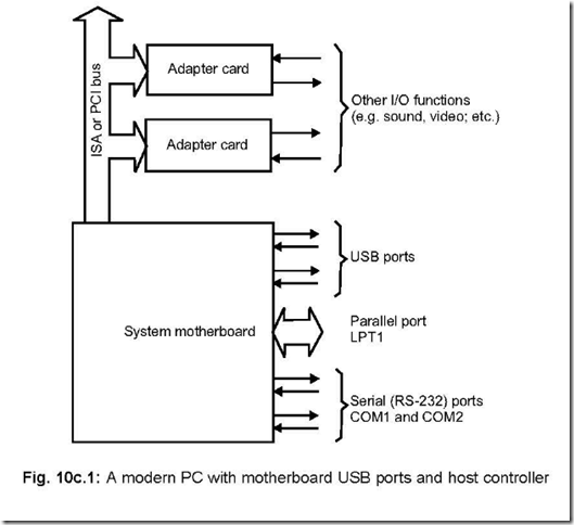
Ans. In modern PC motherboards, USB ports are straightway available, while such facility is made available in older PCs by inserting USB adapter cards. Fig. 10c.1 shows the modern PC version of a motherboard which has the USB ports available from it. Thus the kind of port facilities available from such a motherboard are : USB ports, Parallel ports LPT1 and serial (RS–232) ports COM1 and COM2. For implementing USB standards, PCs must have atleast Windows 98, 2000 or XP version facilities in it.
6. Discuss (a) USB host (b) USB device. Ans. (a) USB host:
A USB host is comprised of the following:
z USB host controller hardware
z USB system software
z Client software
USB system software comprises controller driver, OS and USB driver, while client software has the device driver for the USB device. The USB host:
z detects attachment/detachment of USB devices.
z manages data/control information flow either way between the host and the USB devices.
z keeps track of the status information of the USB devices.
z powers USB devices which don’t have power of their own.
(b) USB device:
A USB device has the following:
z a USB bus interface hardware
z a USB logical device and
z functions, i.e., many capabilities that a USB device can provide.
Again the bus interface hardware comprises a transreceiver and a Serial Interface Engine (SIE). The former provides the electrical requirements while the latter is meant for providing the bit timings on the bus.
The functionalities of a USB device are:
z Responds to all host requests.
z Always monitors the device address in each communication and selects self when the device address matches with that sent by communication from the host.
z When it receives some data, it checks for errors in the error checking bits. If it detects errors, then it requests for retransmission of data. When the device sends data, check bits are added before sending.
7. Explain how USB interface is implemented and also indicate the USB data signals.
Ans. USB uses two lines for differential data connections (designated D+ and D–) and also two lines for supplying power to the cable— one is VBUS (nominal value +5V) and the other customary GND wire.
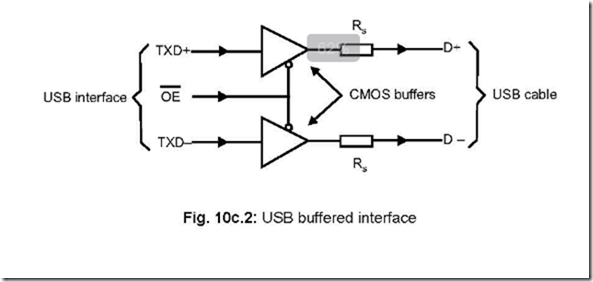
The USB buffered interface is shown in Fig. 10c.2.
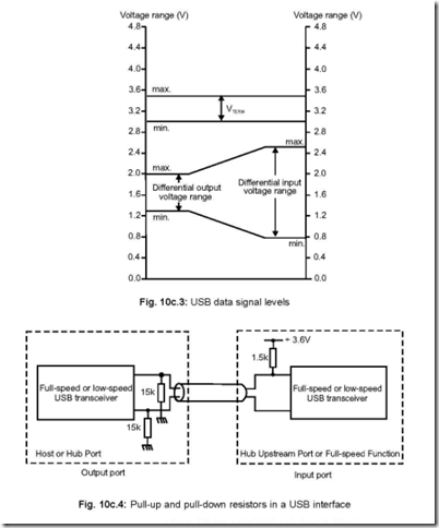
![]() Three lines are input to the CMOS buffers — T X D+, T X D– and OE (output enable). The data signal levels must conform to that shown in Fig. 10c.3. The logic high terminating voltage should have a value in between 3.0– 3.5 V.
Three lines are input to the CMOS buffers — T X D+, T X D– and OE (output enable). The data signal levels must conform to that shown in Fig. 10c.3. The logic high terminating voltage should have a value in between 3.0– 3.5 V.
Pull-up (1.5k) and pull-down (15k) resistors are placed at the input or output of a port,
shown in Fig. 10c.4, and are inserted for detection of device connections.
8. Describe the USB Cable.
Ans. The cross-sectional view of the USB cable is shown in Fig. 10c.5.
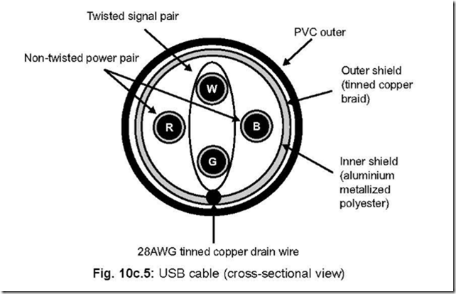 USB cable assemblies are available in three varieties : detachable full-speed captive and low-speed cables. The colours recommended for the cable assembly are white, grey or black.
USB cable consists of four conductors—two for power and two for data. Again two variants are there—full-speed cable and low-speed cable. Full-speed cable consists of twisted pair of conductors for signalling which is not so for low speed cables—because for the latter, noise and electro-magnetic interference are not dominant.
Full-speed cables may be used for low-speed purposes also—but in such a case the full-speed cable must conform to low-speed cable requirements.
9. Discuss the different types of USB connectors.
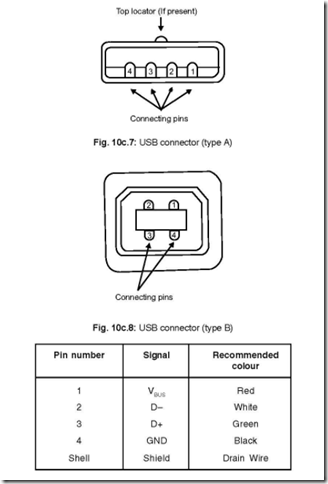
Ans. There are two types of USB connectors—Series A and Series B or Type A and Type B. ‘A’ Type connectors are used in USB devices while ‘B’ type connectors are meant for device vendors in order to provide a standard detachable cable. ‘Keyed connector’ protocol is used by USB.
Fig. 10c.6 shows a typical type ‘A’ connector, showing the standard USB icon and a top locator on the cable end side of the connector.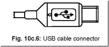
Fig. 10c.6: USB cable connector
Fig. 10c.7 and Fig.10c.8 show respectively Type A and Type B connectors whilst Fig. 10c.9 shows the signals corresponding to the pins and the recommended colour codings also.
Full speed devices use B type connector allowing the device to use detachable USB cable. Thus devices can be built without hardwired cable and cable replacement becomes very easy if the need so arises.
The following gives a comparison between Type A and Type B connectors:
|
Type A connector |
Type B connector |
|
1. Series A plugs are always oriented towards the host. 2. Series A plug mates with series A receptacle. 3. Series A receptacle acts as outputs from host system/hubs. 4. Series A plugs are oriented towards the host. |
1. Series B plugs are always oriented towards the USB device. 2. Series B plug mates with series B receptacle. 3. Series B acts as inputs to hubs/devices. 4. Series B plugs are oriented towards the USB hub/device. |
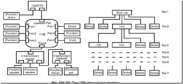
10. Draw and describe the USB topology showing the different layers or tiers. Ans. A tiered star topology is used to connect USB host and the devices and is shown in Fig. 10c.10. A maximum of 127 USB devices can be connected to one USB bus.
11. Discuss bit stuffing and synchronisation field as employed in USB.
Ans. USB devices always employ encoded data for transmission and does not have a separate clock. In such a system, logic 1 is represented by no transition in signal level while logic 0 is represented by a signal transition which is effected at the beginning of the bit interval.
If a given data has long string of 1’s then no transition takes place during this period and the receiver may go out of synchronisation. In such a case, on occurrence of six consecutive 1’s, the transmitter inserts (or stuffs) a 0. Thus a signal transition is forced to occur after the sixth ‘1’ and enables synchronisation between transmitter and receiver. The receiver, on detecting such a 0, discards it.
But stuffing alone cannot always guarantee synchronisation between transmitter and receiver because the host (PC) and the device do not share the same clock. Each packet transmitted by the transmitter begins with a synchronisation field—it is a byte having the form KJKJKJKK. When the receiver detects such a field, it knows that data packets are going to come down the line. A synchronous field per packet is used.
12. How error detection and its possible elimination is done in USB?
Ans. Differential drivers and receivers are employed and shielding of cables are done to enhance data integrity in USB transmission. Error detection is done by employing CRS (Cyclic Redundancy Character) code on control and data fields. Automatic detection of attachment and detachment of devices and system level configuration of resources are some of the other facilities available in the system. Error protection fields are included in each packet of data transmitted to obviate the effects of transients. An error recovery procedure is invoked in hardware or software for cases where data integrity is of prime importance. The procedure includes retransmission of failed data a fixed number of times, beyond which the software is informed about this repeated failures. The software will then try to retrieve the data—as per the application and device function.
13. Discuss the data transfer types possible in USB.
Ans. Four types of data transfers are allowed by USB architecture. These are: control data transfers, bulk data transfers, interrupt data transfers and isochronous data transfers. These are discussed below:
Control data transfers: It is used by the USB system software when a device is first attached to the system. Apart from this, some other driver software can use the control data transfers in some special cases.
Bulk data transfers: Bulk data transfers are generally meant for printers or scanners, etc.—the data transfer being sequential in nature. Data security is ensured at the hardware level and also invoking retries a limited number of times in case of failures. Interrupt data transfers: Some event occurrence, characters, coordinates that are organised as groups of one/or a few bytes fall under this category. Such data from a device may occur at any time.
Isochronous data transfers: If data is continuous and delivered in real-time, then it
is isochronous data. This kind of data must be delivered the moment it is received.
Voice is an example of isochronous data. Two problems may arise when voice data
delivery is undertaken. Assuming data delivered at the appropriate rate by the USB
hardware, delivery delays may be there due to software-degrading real-time applications.
On the other hand, if delivery rate is not maintained, drop-outs may occur due to buffers
or frame underruns or overruns. To ensure proper data delivery, sometimes a part of
the available USB bandwidth is reserved/dedicated for isochronous data transfers.
14. Describe the clock signal associated with USB.
Ans. The clock signal associated with USB is encoded. The form of encoding undertaken is NRZI with bit stuffing. This ensures adequate transitions. Before sending each packet a SYNC field is sent. This is done for the receiver to get itself ready to synchronise itself with the bit recovery clock.
15. Describe how data is transported between host controller and devices via USB. Ans. It is the host controller (i.e., the PC) which initiates all the data transfers on USB. Up to three packets are transmitted for each bus transaction. The host controller sends a
USB packet that contains the type and direction transaction, the device address on the
USB and the endpoint number. This first packet is called a token packet and a must
whenever a transaction is initiated.
The device address which is received by each of the devices on the USB are decoded
and the one whose address matches with the address which has been sent (via the token
packet) is identified on the USB. The token packet also contains the information about
the directions of data flow—i.e., whether from a host to device or vice-versa. The source
then sends the data packet. The destination responds with a handshake packet indicating whether the transfer was successful.
16. What are the different devices available as far as device powering is concerned? Ans. There are two types of devices—bus-powered devices and self-powered devices.
Devices which depend totally on power from the cable are called bus-powered devices
while devices whose power are made available otherwise are called self-powered devices. Devices are powered by the connected hubs and this power may be available from the host controller or from an external power source.
Cables and connectors are such that upstream and downstream connectors are not interchangeable—thus loopback connections at the hubs are not feasible.
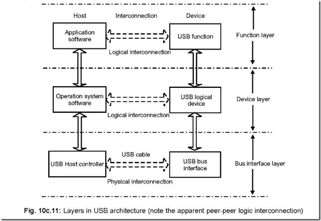
17. Show the different layers in USB architecture and discuss.
Ans. The different layers in the USB architecture are shown in Fig. 10c.11. The different layers shown in the architecture are Bus Interface Layer, Device Layer and Function Layer. The Bus Interface Layer provides physical/signalling/packet connectivity between the host and a device. This layer is the one which undertakes the actual data transfer. Each layer provides peer-to-peer connectivity. The Device Layer establishes logical connectivity between operating system software and USB logical device whereas the Function layer provides logical interconnection between the application software and USB functions.
18. Discuss connection/disconnection of USB devices from the bus.
Ans. Host-connection and host-disconnection of devices from the USB is possible—this is a very vital advantage with USB which is not available with other bus systems. The host’s (PC’s)
software is thus able to recognise the connection/disconnection while it is in service and is able to reconfigure the system dynamically.
Status indicators are available on particular pins of a port attached to a hub that indicate the connection/disconnection of a USB device. The host accesses these pins to get to know the status of a device.
A device, if newly attached, is assigned a particular address by the host and it (the host) determines via software whether the newly attached device is a hub or a function.
When a device is detached from a hub’s port, the hub disables the port and indicate the host about the removal of the device. On the other hand, if the detached device is a hub the system software handles this removal of the hub(s) and or device which are connected to the removed hub.
19. What is enumeration?
Ans. The process of allocating a unique address to a unique device is called enumeration. Since attachment/detachment of devices to USB can take place at any time, hence enumeration is an on-going process as far as the USB system software is concerned.
20. What is meant by Endpoint?
Ans. Information regarding configuration, set-up or data are transported on the USB via buffers of definite size. These buffers are called endpoints. Two types of endpoints are there —IN endpoints and OUT endpoints. The host in the system delivers information into an OUT endpoint (towards the device) and the device delivers information into an IN endpoint (towards the host). An USB device can have a maximum of 16 IN and 16 OUT endpoints.
Again endpoints are of two types—data endpoint and control endpoint. Each endpoint has an unique endpoint number.
21. Discuss packets with regard to data transfer.
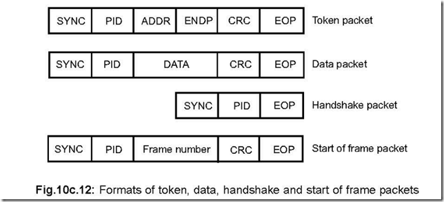
Ans. Information is transferred in packets in USB. Four packet types are used—token, data, handshake and start of frame packets. Each type of packet contains a combination of the following fields:
Synchronization (SYNC)
Packet ID (PID)
Address (ADDR)
Endpoint (ENDP)
Error checking (CRC) and
End of packet (EOP)
SYNC, PID and EOP are common in all the four types of packets.
SYNC is a 1-byte sequence KJKJKJKK. All packets start with SYNC field. PID is also a one byte field that identifies the type of packet being sent. The lower nibble indicates the PLD, while the upper nibble is a complement of the lower one. ADDR is a 7-bit field and contains the address of a function of the USB device for which the packet is meant.On resetting or powering on of a device, the default address becomes 0. It is reprogrammed during enumeration by the host. ENDP is a one nibble field and hence a maximum of 16 endpoints can be addressed. CRC is 5-bit/16-bit for token/data packets respectively. EOP contains two bits in SEO state and is followed by a single bit in J state.
22. Show the formats of the four types of packets and discuss them. Ans. The four types of packets are shown below in Fig. 10c.12.
Token Packet: Token packet is a must for each transaction and is sent by the host controller at the beginning of each transaction. This packet indicates the type of transaction that is to take place. The ADDR (address field) is decoded by the USB device and it selects itself if the address is meant for it. Token packets can be of three types : IN, OUT and SETUP. The first indicates that the host intends to read information while the second indicates that the host would send information. SETUP indicates beginning of transfer of control.
Data Packet: A data packet may contain between 0 to 1023 bytes of data. Four types
of data packets are there : DATA0, DATA1, DATA2 and MDATA. Data transfer takes
place either way from host to device or vice-versa i.e., downstream or upstream. Handshake Packet: It is used for successful reception of data, flow control, halt condition, command acceptance/rejection, etc. It can be of three types : ACK, NAK and
STALL. ACK indicates that the packet has been successfully received while NAK
(negative acknowledgement) indicates data packet not received properly or else the receiver is busy. STALL indicates a function is unable to transmit/receive data.
Start-of-Frame Packet: It is issued by the host at the beginning of each frame. Frame transfer period is 125 µs for high speed and 1 ms for low speed or full speed bus type. The host increments the frame number each time a frame gets transferred. After reaching a value of 7FF H, the frame number rolls over.
23. Describe USB descriptors.
Ans. A hierarchy of descriptors are there for USB devices. These descriptors are data structures. They carry all the informations about a device, how the device is configured, the number as also the types of endpoints a particular device has etc.
The different descriptors are:
z Device descriptors
z Interface descriptors
z Endpoint descriptors
z Configuration descriptors
z String descriptors etc.
To note at this point that all the descriptors have a common format.
