Test 15. Matrix Keypad + serial transmission
Keypads play important role in a small embedded system where human interaction or human input is needed. All we have to do is connect the rows and columns to a port of microcontroller and program the controller to read the input.
We make the rows as i/p and we drive the columns making them o/p, this whole procedure of reading the keyboard is called scanning.
A 3 x 4 matrix keypad is used for data entry. The 12 push switches are connected to seven lines of port A, as shown in figure 36.
Program description
Interrupt Service Routine has not been used in the program.
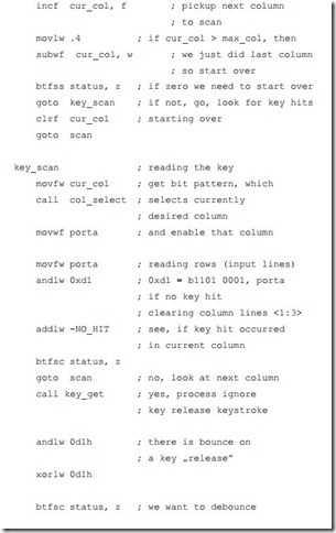
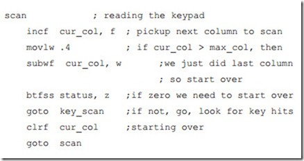
The three columns of the keypad are connected to three of the output signals from the PIC. The four rows of the keypad are connected to four of the input signals to the PIC. If no key is pressed there is no electrical contact between the rows and the columns. The PIC detects which key is pressed by ‘scanning’ the keypad.
First the PIC makes the column 1 current column and sets the signal going to Col- umn 1 low (a digital ‘0’). All the other Columns are made high (a digital ‘1’). Then it tests the input signals coming from each Row in turn. If any of the Row signals is low, this means that the corresponding key in Column 1 has been pressed. Current column number is stored to the variable cur_col.
Interrupt Service Routine has not been used in the program. During the initializa- tion phase the variable cur_col is cleared:
Now if we know valid keys, they have to be translated into ASCII codes. This task carries out the routine key_xlate. The lookup tables are built with the respective values for each column and each row. The lowest ASCII code is for the character
# (ASCII code 35)In lookup tables we assign 0 for the # character and starting with 0 we successively assign next numbers for next characters. Therefore after finishing this procedure to each value we have to add 35.
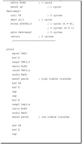
Finaly the found ASCII codes are sent to LCD for displaying and in parallel for transmission to terminal window on PC.


