In-Circuit Debugging
In-circuit debugging (ICD) is the most powerful fault-finding technique available for microcontrollers. It allows the chip to be programmed and tested in circuit using the standard MPLAB debugging tools to control program execution in the actual target board. This is obviously a major advantage, as it allows the interaction of the PIC chip with the real hardware to be more fully examined than in a purely software simulation. Microchip currently offers three main debugging interfaces, of increasing cost and power, which all support the whole range of PIC chips. These are:
• PICkit3
• ICD3
• Real ICE.
They all possess the following features:
• USB connection
• Program download, read and verify
• In-circuit debugging, including
• Unconditional and conditional breakpoints
• Register display and stopwatch timing.
PICkit3 is the most cost-effective solution for non-professional developers, providing all the necessary features for learning and hobby applications in a compact and easy-to-use package. It is an enhanced version of PICkit2, operating at a USB full speed data rate of 12 Mb/ s. It uses the six-pin in-line board connector, which will normally connect direct to the chip in circuit.
ICD3 is more powerful, operating with high-speed USB (up to 480 Mb/s) to provide real-time ICD with maximum MCU clock rates and more complex breakpoint triggering options. It uses the six-pin RJ-11 connector, designed to connect directly to chips that support ICD, or to a header board (see below) for those that do not.
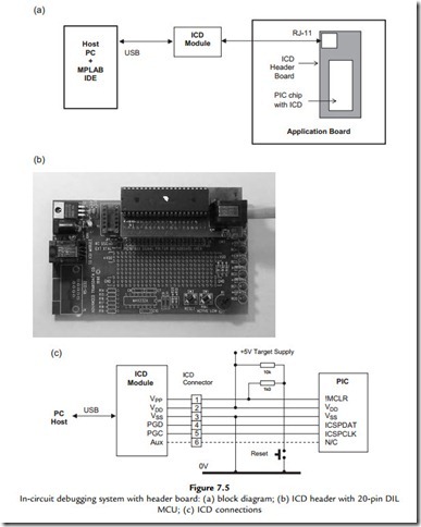
PICkitX and ICDX programmers are both capable of supporting ICD. Unfortunately, the smaller mid-range (16FXXX) chips, including the 16F690 chip fitted in the LPC board, do not support ICD internally, owing to pin-out limitations and cost constraints. For these chips, ICD can be implemented instead by using a header board connected between the ICD module and the chip socket on the application board. The header board carries a version of the target chip that incorporates the on-chip ICD circuitry, which substitutes for the target device while the system is under development (these chips are not available separately).
The ICD header system configuration is shown in Figure 7.5(a). The ICD module sits in between the host PC running MPLAB IDE and the application board MCU socket (Figure 7.5b). When debugging is complete, the chip can be programmed to run independently and plugged directly into the board. The ICD signals are shown in Figure 7.5(c), with definitions provided in Table 7.1. The on-board reset circuit has been included to show how it is isolated from the VPP by a 1k0 resistor.
