Software Design
We can now start work on the software using a flowchart to outline the program. A few simple rules will be used to help devise a working assembly code program; these have been discussed in more detail in Chapter 2.
A program consists of a sequence of instructions that are executed in the order that they appear in the source code, unless there is an instruction or statement that causes a jump, or branch. Usually jumps are ‘conditional’, which means that some input or variable condition is tested and the jump is made, or not, depending on the result. In PIC assembler, ‘Bit Test and Skip if Set/Clear’ and ‘Decrement/Increment File Register and Skip if Zero’ provide conditional branching when used with a ‘GOTO label’ or a ‘CALL label’ immediately following.
A loop can be created by jumping back at least once to a previous instruction. In our standard delay loop, for instance, the program keeps jumping back until a register that is decremented within the loop reaches zero. In high-level languages, conditional operations are created using
IF (a condition is true) THEN (do a sequence), and loops created using statements such as DO (a sequence) WHILE (a condition is true/not true). This terminology can be used in a program outline to clarify the logical sequences required.
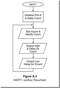
MOT1 Outline Flowchart
Flowcharts illustrate the program sequence, selections and iterations in a pictorial way, using a simple set of symbols. Some basic rules for constructing flowcharts are all that are needed to ensure consistency in their use, leading to well-structured programs. An outline flowchart for the motor speed control program MOT1 is shown in Figure 8.4.
The outline flowchart shows a sequence where the inputs (Run, Speed Up and Speed Down) are checked and the delay count is modified if either of the speed control inputs is active. The output is then set high and low for that cycle, using the calculated delays to give the MSR. The loop repeats endlessly, unless the reset is operated. The reset operation is not represented in the flowchart, because it is an interrupt, and therefore may occur at any time within the loop. The program name, MOT1, is placed in the start terminal symbol. Most programs need some form of initialization process, such as setting up the ports at the beginning of the main program loop. This will normally only need to be executed once. Any assembler directives, such as label equates, should not be represented, as they are not part of the executable
In common with most ‘real-time’ applications, the program loops continuously until reset or switched off. Therefore, there is an unconditional jump at the end of the program back to start, but missing out the initialization sequence. Since no decision is made here, the jump back is simply represented by the arrow, and no process symbol is needed. It is suggested here that the loop back should be drawn on the left side of the chart, and any loop forward on the right, unless it spoils the symmetry of the chart or causes line segment cross-overs. Note that when branching, the flow junctions must be BETWEEN process boxes, to preserve a single input, single output rule for each process. Each process then always starts and ends at the same point.
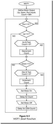
MOT1 Detail Flowchart
The outline flowchart given in Figure 8.4 may show enough information for an experienced programmer. If more detail is needed, boxes in the main program can be elaborated until there is enough detail for the less experienced programmer to translate the sequence into assembly code. A detail flowchart is shown in Figure 8.5.
After the initialization sequence, a set of conditional jumps is required to enable the motor, check the ‘up’ and ‘down’ inputs, and test for the maximum and minimum values of the value of ‘Count’ (FF and 01). Two different forms of the decision box have been used in this example, both of which may be seen. The diamond-shaped decision symbol is used here to represent a ‘Bit Test and Skip If Zero/Not Zero’ operation, while the elongated symbol represents an ‘Increment/Decrement and Test for Zero’ operation, which essentially combines two instructions in one. In either case, the decision box should contain a question, with its outputs representing a ‘Yes’ or ‘No’ result of the test. Note that only the result producing the jump needs to be specified.
‘Decrement and Skip if Zero’ is used to create the software delay loop. Two different delays are required, one for the mark time, one for the space. Since the delay needed is relatively short, and only a single loop is needed, a delay subroutine is not necessary.
Flowchart Symbols
A minimal set of flowchart symbols is shown in Figure 8.6. The data flowchart symbols provided in Word (Autoshapes) may be used, but they do not necessarily have the same meaning here. The text can be inserted via the drawing object properties menu (right click, add text).
Terminals
These symbols are used to start or end the main program or a subroutine. The program name or routine start label used in the source code should be specified in the start box. If the program loops endlessly the END symbol is not needed, but RETURN must always be used to terminate a subroutine. In PIC programming, use the project name (e.g. MOT1) in the start symbol of the
main program, and the subroutine start address label in subroutine start symbols. Terminals have only one input or output.
Processes
The process box is a general purpose symbol that represents a sequence of instructions, possibly including loops inside it. The top-level flowchart of a complex program can be simplified, with a lot of detail concealed in each box. A subroutine is a process that will be implemented in the source code as a separate block, and may be used more than once within a program. It may be expanded into a separate subroutine flowchart, using the same name in the start symbol as that shown in the calling process. Subroutines can be created at several levels in a complex program. Processes should have only one input and one output.
Input/Output
This represents processes whose main function is input or output using a port data register in the microcontroller. Use a statement in the box that describes the general effect of the I/O operation, for example, ‘Switch Motor On’ rather than ‘Set RA0’. This will make the flowchart easier to understand. This symbol should also have only one input and one output.
Decisions
The decision symbol contains a description of the conditional branch as a question. There will be two alternative exit paths, for the answers ‘yes’ and ‘no’. Only the arrow looping back
or forward needs to be labeled ‘yes’ or ‘no’; the default option, which continues the program flow down the center of the chart, need not be labeled. In PIC assembly language, this symbol would refer to the ‘Test and Skip’ instructions. In the MOT1 detailed flowchart, an enlarged decision box is used to represent the ‘Decrement/Increment and Skip if Zero’ operation. This symbol allows more text inside, so is a useful alternative to the standard diamond shape. The decision symbol thus contains a logical question, and has one input and two outputs, ‘yes’ or ‘no’.
Flowchart Structure
In order to preserve good program structure, there should be single entry and exit points to and from all process blocks, as illustrated in the complete flowcharts. Loops should rejoin the main flow between symbols, and not connect into the side of a process symbol, as is sometimes seen. Terminal symbols have a single entry or exit point. Decisions in assembler programs only have two outcomes, branch or not, giving two exits. Loops back should be drawn on the left of the main flow, and loops forward on the right of the main flow, if possible. For the main flow down the page, the arrowheads may be omitted as forward flow is clearly implied.
Connections between pages are sometimes used in flowcharts, shown by a circular labeled symbol. It is recommended here that such connections be avoided; it should be possible to represent a well-structured program with a set of separate flowcharts, each of which should fit on one page. An outline flowchart should be devised for the main sequence, and then each process detailed with a separate flowchart, so that each process can be implemented as a subroutine or macro. In this case, the main program sequence should be as small as possible, consisting of subroutine calls and the main branching operations.
Therefore, the program should initially be represented as an outline flowchart on a single page, and each process expanded using subroutines or functions on separate pages. Keep expanding the detail until each block can be readily converted to source code statements. A well- structured program like this will be easier to debug and modify. Subroutines can be ‘nested’, to a depth that depends on the MCU hardware stack size (including interrupts). Mid-range PICs have space for eight return addresses in a hardware stack, which means that only eight levels of subroutine or interrupt are allowed.
Structure Chart
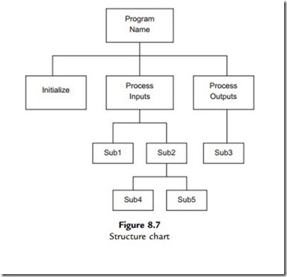
The structure chart is another method for representing complex programs. Each program
block is placed in a hierarchical diagram to show how it relates to the rest of the program. This technique is most commonly used in data processing and business applications running on larger computer systems, but may be useful for more ambitious microcontroller applications.
The program shown in the structure diagram (Figure 8.7) has four levels. The main program calls subroutines to initialize, process inputs and process outputs. The input processing routine in turn calls Sub1 and Sub2 subroutines. Output processing only requires Sub3, but Sub2 calls Sub4 and Sub5 at the lowest level. At this level, 3 stack locations will be used up.
Pseudocode
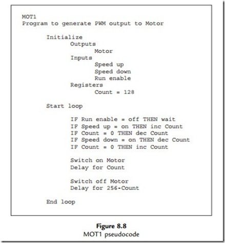
Pseudocode is a text outline of the program design. The main operations are written as descriptive statements that are arranged as functional blocks. The structure and sequence are represented by suitable indentation of the blocks, as is the convention for high-level languages. An outline of MOT1 is shown in Figure 8.8.
The pseudocode version of the program uses high-level style syntax, such as IF … THEN, to describe the selections in the program. It has the advantage that no drawing is required, and the
pseudocode can be entered directly into the text editor used for writing the source code. It can be started as a brief outline and developed in stages, until it is ready to be translated into assembler syntax. The pseudocode can be left in the source code as the basis of program comments, or replaced, whichever suits the programmer. Although used here to represent an assembler program, pseudocode is probably most useful for developing ‘C’ programs for applications for the more powerful PIC microcontrollers.


