Hardware delay
Context
● You are developing an embedded application using one or more members of the 8051 family of microcontrollers.
● You are designing an appropriate software foundation for your application.
Problem
You need to wait for a fixed period of time (measured in milliseconds) before taking some action.
Background
—
Solution
All members of the 8051 family have at least two 16-bit timer / counters, known as Timer 0 and Timer 1. These timers can be used to generate accurate delays.
We begin by providing brief information on these timers.
Timer 0 and Timer 1
Timer 0 and Timer 1 have much in common and we will consider them together.
To see how these timers operate, we need, first, to introduce the TCON SFR (Table 11.1).
(Cleared by hardware if processor vectors to interrupt routine.)
TR1 Timer 1 run control bit
Set/ cleared by software to turn Timer 1 either ‘ON’ or ‘OFF’.
TF0 Timer 0 overflow flag
Set by hardware on Timer 0 overflow.
(Cleared by hardware if processor vectors to interrupt routine.)
TR0 Timer 0 run control bit
Set / cleared by software to turn Timer 0 either ‘ON’ or ‘OFF’.
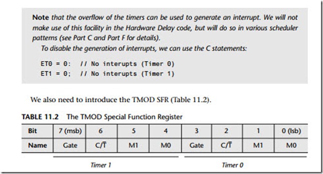
Note that the overflow of the timers can be used to generate an interrupt. We will not make use of this facility in the Hardware Delay code, but will do so in various scheduler patterns (see Part C and Part F for details).
To disable the generation of interrupts, we can use the C statements:
The first thing to note in TMOD is that there are three main modes of operation (for each timer), set using the M1 and M0 bits. We will only be concerned in this book with Mode 1 and Mode 2, which operate in the same way for both Timer 0 and Timer 1, as follows:
Mode 1 (M1 = 0; M0 = 1)
16-bit timer/counter (with manual reload).1
Mode 2 (M1 = 1; M0 = 0)
8-bit timer/counter (with 8-bit auto-reload).1
The remaining bits in TMOD have the following purpose:
GATE Gating control
When set, timer/counter ‘x’ is enabled only while ‘INT x’ pin is high and ‘TRx’ con- trol bit is set. When cleared timer ‘x’ is enabled whenever ‘TRx’ control bit is set.
C/T
Counter or timer select bit
Set for counter operation (inputfrom ‘Tx’ input pin).
Cleared for timer operation (input from internal system clock).
Finally, before we can see how this hardware can be used to create delays, you need to be aware that there are an additional two registers associated with each timer: these are known as TL0 and TH0, and TL1 and TH1. These ‘L’ and ‘H’ refer to ‘low’ and ‘high’ bytes, as will become clear shortly.
Creating delays with Timer 0 and Timer 1
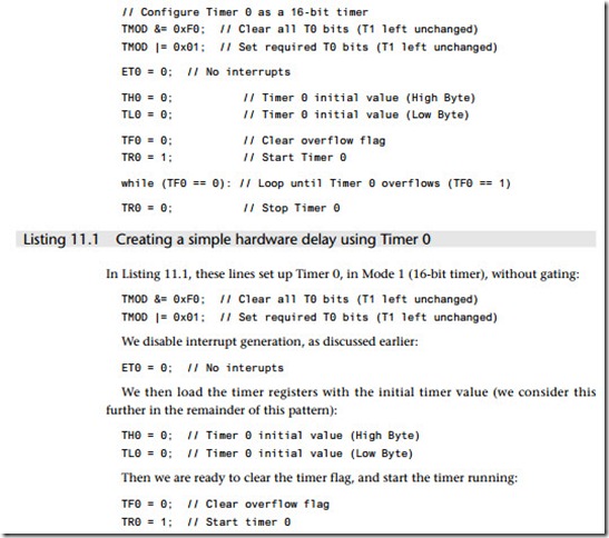
To see how this all fits together, we will consider a concrete example (Listing 11.1).
What happens now in the original 8051 (we consider some exceptions under ‘Portability’) is that the timer will be incremented every 12 oscillator cycles. When this (16-bit) timer overflows – that is, it is incremented from a value of 65535 – the timer flag (TF1) will be set. In addition, as we have already noted, this overflow can be used to generate an interrupt; we do not use this option here.
This is very useful behaviour. Simply by varying the initial value stored in the timer, we specify the number of oscillations that occur before an overflow takes place and can generate shorter delays.
Building on the material discussed under ‘Background’, HARDW ARE DELA Y calcula- tions generally take the following form:
● We calculate the required starting value for the timer.
● We load this value into Timer 0 or Timer 1.
● We start the timer.
● The timer will be incremented, without software intervention, at a rate determined by the oscillator frequency; we wait for the timer to reach its maximum value and ‘roll over’.
● The rolling over of the timer signals the end of the delay by changing the value of a flag variable.
● With a 12-oscillator per instruction 8051, running at 12 MHz, the longest delay that can be produced with a 16-bit timer is ~65 ms. If we need longer delays, we can repeat the process.
Overall, this is a powerful and reliable technique and can be used to generate repeatable delays with good levels of accuracy. A detailed code example is presented later in this pattern.
Why not use Timer 2?
In many cases, as we saw in Chapter 3, modern 8051 family devices are based on the slightly later 8052 architecture: such devices include an extra, more powerful timer (called, logically, Timer 2).
While Timer 2 can be used to generate delays (in a manner nearly identical to that used with Timer 0 and Timer 1 in this pattern), this is generally an inappropriate use for this resource. This is because Timer 2 is a 16-bit auto-reload timer. This auto-reload feature has no value in the generation of delays, but makes it ideally suited as a source of ‘ticks’ for the schedulers we use throughout most of this book.2
Hardware resource implications
H ARDW ARE D ELA Y requires non-exclusive use of a timer. There are often competing demands for such resources, since they are essential for driving a scheduler and are often used, for example, to generate timeouts (see HARDW ARE TIMEOUT [page 305]), for pulse-width modulation (see 3– LEVEL PWM [page 822]), for pulse-rate modulation
(see HARDW ARE PRM [page 742]) and for pulse counting (see HARDW ARE PULSE – COUNT
Reliability and safety implications
The techniques discussed in HARDW ARE DELA Y are generally more portable and more accurate than software-based delays, but they are still not suitable for generating pre- cisely timed delays without careful hand-tuning to take into account factors such as the time taken to call the delay function and the time taken to load the timer with the initial count value.
Delays generated through multiple calls to a delay function will increase the impact of these factors; long delays generated using this technique are likely to be particularly inaccurate.
Portability
We consider two main portability issues here.
Differences in timer increment rates
In the original 8051 (and in most current 8051s), Timer 0 and Timer 1 are incre- mented every 12 oscillator cycles: that is, at 1 MHz in a device using a 12 MHz crystal oscillator. In more recent 8051 devices, factors of 6, 4 or 1 are also used. You must check the data sheet to ensure that your calculations of the initial reload values take these differences into account.
Note that the library code (listed later) is itself highly portable, because it makes use of information provided in the PROJECT HEADER [page 169] file.
Porting within the 8051 family
There are limited timers available in the 8051 family. Careful use of particular timers can help make your code easier to port.
For example, in many applications presented in this book, we will use Timer 2 (where available) to drive a scheduler (see, for example, Chapter 13). In addition, in some appli- cations, Timer 1 will be required to generate baud rates, for a serial network. As a result, your delay code will be particularly portable if you base it on Timer 0.
Note that, where you will use a scheduler and a serial link and your chosen micro- controller does not have Timer 2 available, you may need to use both the available timers for the scheduler (T0) and baud rate generation (T1). You will then be forced to use an implementation of SOFTW ARE DELA Y [page 179] for any necessary delay gener- ation. Note also that, in many cases, the use of a scheduler can remove the need for most delay calculations.
Finally, note that, in addition to Timer 2, some extended 8051s have an additional internal timer, intended for use as an internal baud rate generator: this can free Timer 1 for other purposes, such as delay generation. (See Chapter 3 for details.)
Porting beyond the 8051 family
Like the 8051 family, most microcontrollers have on-board timers: where such timers are available, this pattern may be adapted without great difficulty. If your chosen microcontroller does not have an on-board timer, the pattern SOFTW ARE DELA Y [page 206] offers an alternative solution.
Overall strengths and weaknesses
These basic time delay techniques have the great advantage that they are very simple and can be implemented in a few lines of code. As a result, they are widely applicable and are frequently used in applications where very accurate timing is not of great concern.
![]() They are not suitable for generating very short delays; see ‘Related patterns and alternative solutions’ for alternative suggestions.
They are not suitable for generating very short delays; see ‘Related patterns and alternative solutions’ for alternative suggestions.
Because of the need to manually reload the initial timer value, the delays obtained may not be precisely as expected. This is of particular concern where, for example, an attempt is made to delay for (say) a second by invoking a 50 ms delay 20 times: this will not be accurate. Do not attempt to use HARDW ARE DELA Y to implement a real-time clock!
They require access to an important hardware resource (a timer).
The timings are not very portable: even different members of the 8051 family have different relationships between crystal frequency and instruction cycle fre- quency (note, however, that the code that follows addresses this problem for a wide range of delays).
As implemented here, the processor is tied up waiting for the timer to overflow. Where processor power is limited, this may not be an acceptable solution: use of a scheduler (see Chapter 13) can often reduce the need to waste CPU time in this way.
Related patterns and alternative solutions
The code we present in this pattern is designed to generate delays on N millisecond duration, which is a key requirement in many applications. If this is not what you require, then some alternatives are as follows:
● To generate delays from ~10 µs to about ~10+ ms, HARDW ARE TIMEOUT [page 305] can be used very effectively.
● For generating delays less than ~10 µs, neither HARDW ARE DELA Y nor HARDW ARE T IMEOUT – both of which use Timer 0 / Timer 1 – is suitable. For example, in an original 12 MHz 8051, the minimum timer increment is, in theory, 1 µs: that is the oscillator frequency / 12. However, this delay will often be less than the time taken to call the delay function, set up and start the timer. In general, delays less than
around 10 µs are better implemented in software: see SOFTW ARE DELA Y [page 206] (and LOOP TIMEOUT [page 298]).
● Delays waste CPU time and it is better to avoid using them at all, if possible: see CO – OPERA TIVE SCHEDULER [page 255] for a delay-free alternative that will work in many circumstances.
Example: Generic delay code
Flashing an LED can be useful as a means of drawing attention to a particular warning message or error condition. It can also be used as a means of saving power. There are, of course, numerous different ways of implementing such behaviour: here, we illus- trate the use of the HARDW ARE DELA Y pattern.
Hardware
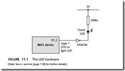
The single LED (or a similar device, such as a buzzer) is assumed to be connected to an 8051 microcontroller on Port 1 (P1.2), using positive logic: that is, +5V lights the LED (Figure 11.1).
Software
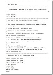
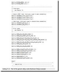
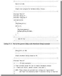
Here we use some generic delay code. This allows the initial timer values to be ‘auto- matically’ determined for a wide range of different hardware and oscillator combinations, by means of the project header file (Main.H), and some appropriate use of the C pre-processor directives.
The key files required in the project follow (Listings 11.2 to 11.4). As usual com- plete set of files are included on the CD.

