Assembly Language
It should be apparent that writing the machine code manually for any but the most trivial applications is going to be a bit tedious. Not only do the actual hex instruction codes have to be worked out, but so do jump destination addresses and so on. In addition, the codes are not easy to recognize or remember.
Mnemonics
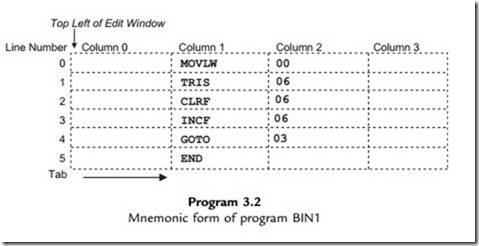
For this reason, simple microcontroller programs are written in assembly language, not machine code. Each instruction has a corresponding mnemonic defined in the instruction set. The main task of the assembler program supplied with the chip is to convert a source code program written in mnemonic form into the equivalent machine code. The mnemonic form of the program BIN1 is shown in Program 3.2.
The instructions can now written as recognizable (when you get used to them!) code words. The program is typed into a text editor, spaced out as shown, using the tab key to place the code in the correct columns. Note that the first column (column 0) is kept blank; we will see why later. The instruction mnemonics are placed in column 1, and the operands (data to be operated on) in column 2. The operand 00 is the data direction code for the port initialization, 06 is the file register number of the port data register, and 03 is the jump destination address, line 3 of the program. The PIC instructions are all 14 bits long, so each line of source code becomes a 14-bit code, which we have already seen. The meaning of the mnemonics is as follows:
The END statement is an assembler directive; it tells the assembler that this is the end of the program, and is not converted into an actual instruction. When entering the program, there must be space before and after each instruction mnemonic, and it is advisable to lay out the program in columns as shown to improve its readability.
Assembly
The source code program could be created using a general purpose text editor, but is normally edited within a dedicated software package such as MPLAB, the PIC integrated development environment (IDE), which contains the assembler as well as a text editor. ISIS schematic capture also incorporates a suitable text editor, which can be opened after the circuit drawing has been completed, or it can be run in conjunction with MPLAB.
The source code text is entered in an edit window and the assembler invoked from the menu. The assembler program analyzes the source code, character by character, and works out the binary code required for each instruction. The terminology can be confusing here; the assembly language application program (user source code) is created in the text editor, while the software tool that performs the conversion is the assembler program or utility.
The source code is saved on disk as a text file called PROGNAME.ASM, where ‘progname’ represents any suitable filename. This is then converted by the assembler program MPASM.EXE, which creates the machine code file PROGNAME.HEX. This appears as hexadecimal code when listed. At the same time, PROGNAME.LST, the list file, is created, containing both the source and hex code, which may be useful later on when debugging (fault finding) the program, we have already seen KEY690.LST in Chapter 1. This assembly and download process will be described in more detail in the next chapter.
Labels
The mnemonic form of the program with numerical operands can now be further improved. We want the operands to be specified in a more easily recognizable form, in the same way that the mnemonics represent the instruction codes. Therefore, the assembler is designed to recognize labels.
A label is a word that represents a number, which can be an address, register or literal. Examples used below are ‘again’, ‘portb’ and ‘allout’. These are listed at the top of the program with the replacement value, and the assembler simply replaces any occurrence of the label with the corresponding number.
Jump destinations are similarly defined by label, by placing the label at the beginning of the destination line, and using a matching label as the jump instruction operand. When the program is assembled, the assembler notes the numerical address of the instruction where the label was found, and replaces the label, when found as an operand, with this address.
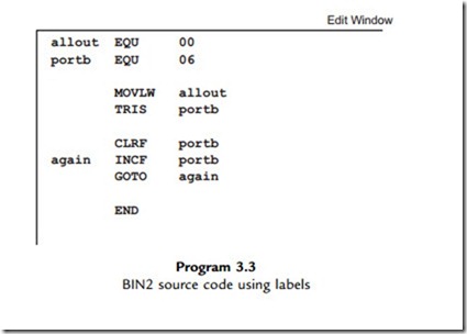
The program BIN1 can thus be rewritten using labels as shown in BIN2 source code (Program 3.3). The literal value 00 and the port register address 06 have been replaced with labels, which are assigned at the beginning of the program. The ‘equate’ statements define the numbers that are to be replaced in the source code. In this case, the label ‘allout’ will represent the port B data direction code, while the data register address itself, 06, will be
represented by the label ‘portb’. ‘EQU’ is another example of an assembler directive, which is an instruction to the assembler program and will not be translated into code in the executable program.
Note that lower case is used for the labels, while upper case is used for the instruction mnemonics and assembler directives. Although this is not obligatory, this convention will be used because the instruction mnemonics are given in upper case in the instruction set. The labels can then be distinguished by using lower case. The jump destination label is simply defined by placing it in column 0 of the line containing the destination instruction. The ‘GOTO label’ instruction then uses a matching label. Initially, labels will be limited to six characters; they must start with a letter, but can contain numbers, e.g. ‘loop1’. Longer labels may be used if preferred.
The programs BIN1 and BIN2 are functionally identical, and the machine code will be the same.
Layout and Comments
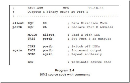
A final version of BIN2 (Program 3.4) includes comments in the program to explain the action of each line, and the overall program. As much information as possible should be provided. When learning programming, comments help the learner to retain information, and when developing real applications, it will help with future modifications and upgrading or software maintenance. Even if you have written the program yourself, you may have forgotten how it works later on!
Comments must be preceded by a semicolon (;), which tells the assembler to ignore the rest of that line. Comments and information can thus occupy a whole line, or can be added after
each instruction in column 3. A minimal header has been added to BIN2, with the source code file name, author and date, and a comment added to each line. Blank lines can be used without a comment ‘delimiter’ (the semicolon); these are used to break up the source code into functional sections, and thus make the structure of the program easier to understand. In BIN2.ASM, the first block contains the operand label equates, the second the port initialization and the third the output sequence. The layout of the source code is very important in showing how it works.
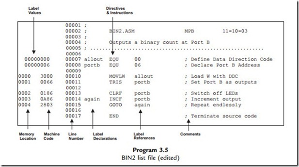
The list file for the program BIN2 is provided as Program 3.5. It contains the source code, machine code and program memory addresses in one file. It has been edited to remove extraneous detail; the original may be downloaded from www.picmicros.org.uk with all the other demo application filesets. A complete list file may be seen in Table 4.4 (Chapter 4).
We now have a program that can be entered into a text editor, assembled and downloaded to the PIC chip. The exact method will vary with the development system you are using. Next, we will look in more detail at developing the program.
. State the four-digit hex code for the instruction INCF 06. (2)
2. State the two-digit hex code for the instruction MOVLW. (2)
3. What is the meaning of the least significant two digits in the PIC machine code
instruction 2803? (2)
4. Why must the instruction mnemonic be in the second column of the source code? (2)
5. Give two examples of a PIC assembler directive. Why are they not represented in the machine code? (3)
6. What are the numerical values of the labels ‘allout’ and ‘again’ in BIN2? (2)
7. A line from the list file for BIN2 is shown below. Explain the significance of each item. (6)
0003 0A86 00014 again INCF portb
8. State the function and origin of program files with the extension: (a) ASM, (b) HEX,
(c) LST. (6)
Answers on page 419. (Total 25 marks)
Activities 3
1. Check the machine code for BIN1 against the information given in the PIC instruction set in the data sheet, so that you could, if necessary, write a program entirely in machine code. Modify the machine code program by deleting the ‘Clear Port B’ operation and changing the ‘Increment Port B’ to ‘Decrement Port B’. What would be the effect at the output when the program was run? Suggest an alternative to the instruction MOVLW 00 which would have the same effect.
2. Refer to Appendix E for a guide to using Proteus VSM to simulate the circuit. You will need a version of Proteus that includes the working model of the 16F84A chip. Enter or download the schematic BIN.DSN into ISIS and attach the program BIN1.ASM. Check that it assembles and runs correctly. Display the SFRs and source code. Set the MCU simulated clock to 100 kHz and single step the program. Observe the execution sequence, and check that the time taken to complete one loop is 120 ms.
3. Enter the program BIN2, using labels, into the text editor, assemble and test as above. Display or print out the list file BIN2.LST and check that the machine code generated is the same as BIN1. Note that there is no machine code generated for comment lines or assembler directives.
If necessary, refer forward to relevant sections to complete these activities.


