8087 Numeric Data Processor
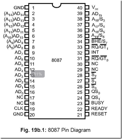
1. Draw the pin connection diagram of 8087. Ans. The pin diagram of 8087 is shown in Fig. 19b.1.
2. What are the characteristics of 8087 NDP?
Ans. The following are the characteristic features of 8087 NDP:
z It can add arithmetic, trigonometric, exponential and logarithmic instructions to the
8086 instruction set for all data types.
z 8087 can handle seven data types. These are : 16, 32, 64-bit integers, 32, 64, 80-bit
floating point and 18–digit BCD operands.
z It has three clock speeds: 5 MHz (8087), 8 MHz (8087–2) and 10 MHz (8087–1)
z It can add 8 × 80-bit individually addressable register stack to the 8086 architecture.
z Multibus system compatiable interface.
z Seven numbers built-in exception handling functions.
z Compatible with IEEE floating point standard 754.
z It adds 68 mnemonics to the 8086 instruction set.
z Fabricated with HMOS III technology and packaged in a 40-pin cerdip package.
3. Draw the architecture of 8087.
Ans. The architecture of 8087 is shown below in Fig. 19b.2.
4. How does 8086 view 8087 NDP?
Ans. At the hardware level, 8086 treats 8087 as an extension to its own CPU capability— providing for registers, data types, control and instruction capabilities.
At the software level, both 8086 and 8087 are viewed as a single unified processor.
5. Discuss A16/S3 to A19/S6 signals.
Ans. When 8086 CPU is in control of buses, these four lines act as input lines, which 8087 monitors.
When 8087 controls the buses, these are the four most significant address lines (A19 to A16) for memory operations during T1. Also, during T2, T3, Tw and T4, status information is available on these four lines. During these states, S6, S4 and S3 are high while S5 is always low.
6. ![]()
![]()
![]() Discuss the S2, S1 and S0 signals.
Discuss the S2, S1 and S0 signals.
Ans. These three signals act as both input or output pins.
When the CPU is active, i.e., CPU is in control of buses, these three signals act as
input pins to 8087. 8087 monitors these signals coming from 8086.
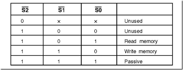
When 8087 is driving, these three status lines act as output pins and are encoded as
follows:
The status lines are driven active during T4, remains valid during T1 and T2 and returns to passive state (111) in T3 or Tw, when READY is high. The status on these lines are monitored by 8288 to generate all memory access control signals.
7. What language 8087 supports?
Ans. 8087 supports the high level languages of 8086 which are: ASM-86, PL/M-86, FORTRAN-86 and PASCAL-86.
8. How 8-bit and 16-bit hosts are taken care of by 8087?
Ans. For 8-bit and 16-bit hosts, all memory operations are performed as byte or word operations respectively.
![]()
![]() 8087 determines the bus width during a system reset by monitoring pin 34 (BHE / S7) of 8087. For 16-bit hosts a word access from memory locations FFFF0 H (a dedicated location) is performed and pin 34 ( BHE ) will be low while, for a 8-bit host, a byte access
8087 determines the bus width during a system reset by monitoring pin 34 (BHE / S7) of 8087. For 16-bit hosts a word access from memory locations FFFF0 H (a dedicated location) is performed and pin 34 ( BHE ) will be low while, for a 8-bit host, a byte access
![]() from the same memory location FFFF0 H is performed and pin 34 ( SS0 ) will be high.
from the same memory location FFFF0 H is performed and pin 34 ( SS0 ) will be high.
9. What is the operating frequency of 8087?
Ans. 8087 operates at frequencies of 5 MHz, 8 MHz and 10 MHz.
10. What is the utility of having NDP 8087 along with 8086?
Ans. 8086 is a general purpose microprocessor suitable mostly for data processing applications.
But in cases where scientific and other calculation-intensive applications are involved,
8086 fails with its integer arithmetic and four basic math function capabilities.
8087 can process fractional number system and transcendental math functions with
its special coprocessor instructions in parallel with the host CPU—thus relieving 8086
with these tasks. In Intel number scheme, 8086/8087 system is known as an iAPX86/20
two-chip CPU.
11. What are the two units in NDP and what do they do?
Ans. There are two units in 8087—a Control Unit (CU) and a Numeric Execution Unit (NEU).
These two units can operate independently i.e., asynchronously—like the BIU and
EU of 8086.
The CU receives, decodes instructions, reads and writes memory operands and
executes all other control instructions. NEU does the job of arithmetic processing. The
control unit establishes the communication between the CPU and memory and
coordinates the internal processor activities.
12. How 8086 communicates with NDP 8087?
![]()
![]()
![]() Ans. The opcodes for 8087 are written into memory along with those for 8086. As 8086 (host) fetches instructions from memory, 8087 also does the same. These prefetched instructions
Ans. The opcodes for 8087 are written into memory along with those for 8086. As 8086 (host) fetches instructions from memory, 8087 also does the same. These prefetched instructions
are put into the queue of both 8086 and 8087, while S0 , S1
information on bus status.
and S2
provide the
When an ESC instruction is encountered by the host (8086), it calculates the effective
address (EA) and performs a ‘dummy’ read cycle. The data read is not stored. However,
a read or write cycle is performed by 8087 from this EA. 8087 does not have any facility
to generate EA on its own. If the coprocessor instruction does not need any memory
operand, then it is directly executed by 8087.
Several data formats as used by 8087 require multiple word memory operands. In such
cases, 8087 need to have the buses under its own control. This is achieved via RQ/GT
line. The sequence is as follows:
z 8087 sends out a low going pulse on its RQ/GT pin (connected to the RQ/GT pin of
8086) of one clock pulse duration.
z 8087 waits for the grant pulse from the host (8086).
z When it is received by 8087, it increments the address and outputs the incremented
address on the address bus.
z 8087 continues memory-read or memory-write signals until all the instructions meant
for 8087 are complete.
z At this point, another low going pulse is sent out by 8087 (to 8086) on its RQ/GT line,
to let 8086 know that it can have the buses back again.
When the NEU (numeric execution unit) begins executing arithmetic, logical,
transcendental and data transfer instructions, it (8087) pulls up BUSY signal. This output
![]() signal of 8087 is connected to the TEST input of 8086. This forces 8086 to wait until the
signal of 8087 is connected to the TEST input of 8086. This forces 8086 to wait until the
![]() TEST input of 8086 goes low (i.e., BUSY output of 8087 becomes low).
TEST input of 8086 goes low (i.e., BUSY output of 8087 becomes low).
The microcode control unit of 8087 generates the control signals for execution of instructions while the ‘programmable shifter’ shifts the operands, during the execution of instructions like FMUL and EDIV. The data bus interfaces the internal data bus of 8087 with the data bus of the host (8086).
13. What INT output signal does?
Ans. This interrupt output is utilised by 8087 to indicate that an unmasked exception has been received during excitation by 8087. This is normally handled by 8259A.
14. ![]() Discuss the BHE/S7 signal of 8087.
Discuss the BHE/S7 signal of 8087.
![]() Ans. During T1 cycle, BHE / S7 output pin used to enable data on the higher byte of the 8086 data bus. During T2, T3, Tw and T4, this pin becomes the status line S7.
Ans. During T1 cycle, BHE / S7 output pin used to enable data on the higher byte of the 8086 data bus. During T2, T3, Tw and T4, this pin becomes the status line S7.
15. What kind of errors/exception conditions 8087 can check?
Ans. During execution of instructions, 8087 can check the following kind of errors/exception conditions:
z Invalid operation: This includes the attempt to calculate the square root of a negative number or say to take out an operand from an empty register. Also included in this category are stack overflow, stack underflow, indeterminate form or the use of a non-number as an operand.
z Overflow: Exponent of the result is too large for the destination real format.
z Zero divide: Arises when divisor is zero while the dividend is a non-infinite,
non-zero number.
z Denormalised: It arises when an attempt is made to operate on an operand that
is yet to be normalised.
z Under flow: Exponent of the result is too small to be represented.
z Precision: In case the operand is not made to represent in the destination format,
causing 8087 to round the result.
16. What does 8087 do in case an exception occurs?
Ans. 8087 sets the appropriate flag bit in the status word in case of occurrence of any one of the exception conditions. The exception mask in the control register is then checked and if the mask bit is set i.e., masked, then a built-in fix-up procedure is followed.
If the exception is unmasked (i.e., mask bit = 0), then user-written exception handlers take care of such situations. This is done by using the INT pin which is normally connected to one of the interrupt input pins of 8259A PIC.
17. Describe the register set of 8087.
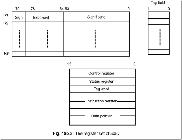
Ans. The register set of 8087 comprises the following:
z Eight data registers—each 80-bits wide
z A tag field R1–R8.
z Five control/status registers.
The register set of 8087 is shown in Fig. 19b.3.
The eight data registers, residing in NEU, can be used as a stack or a set of general registers. These registers are divided into three fields—sign (1-bit), exponent (15-bits) and significand (64-bits). Corresponding to each of these eight registers, there is a two bit TAG field to indicate the status of contents.
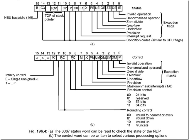
The control and status registers are shown in Fig. 19b.4. The top bits in the status register indicate the register currently at the top of the register stack. Bits 0–5 indicate the ‘exception’ status, while the condition code bits C2 – C0 are set by various 8087 operations similar to the flags within the CPU.
Bits 0 – 5 of the control word register allow any of the exception cases to be masked. Bit 6 is a ‘don’t care’ bit while bit 7 must be reset (low) for the interrupts to be accepted. The upper bits of the control register defines type of infinity, rounding and precision to be used when 8087 performs the calculations.
The control register defines the type of infinity, rounding and precision to be used
when NDP performs and executes the instructions. For the interrupts to be accepted,
bit 7 must be reset while bits 0–5 allow any of the exception cased to be masked.
Both the Data & Instruction pointer registers are 20-bits wide. Whenever the NEU executes an instruction, CU saves the opcode and memory address corresponding to this instructions and also its operand in these registers. For this, a control instruction is needed for their contents to be stored in memory and is utilised for program debugging.
Initially, Data registers of 8087 are considered to be empty, unlike the CPU registers. The data written into these registers can be valid (i.e., the register holds a valid data in temporary real format), zero or special (indefinite due to error). Each data register has a tag field associated with the corresponding register. Each tag field is two bit wide and contains one of the four states that each of the data registers can hold. The eight numbers of 2-bit tag field again are grouped into a single tag word—it is thus 16-bit wide. It optimises the NDP’s performance under certain conditions and normally needed by the programmer.


