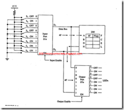
Data Copy Between Accumulator and I/Os
In the Z80 instruction set, input and output devices are identified by 8-bit addresses, The set includes several instructions that can read data from an in put device (also known as input port) and write data into an output device (or output port). Two of these I/O instructions are described here:
|
Opcode |
Operand |
Bytes |
Description |
|
IN |
A, (8-bit) |
2 |
Read data from an input port into the accumulator. |
|
OUT |
(8-bit), A |
2 |
Write data to an output port from the accumulator. |
General Characteristics
I. These I/O instructions do not affect flags. (Some Z80 l/O instructions do affect flags; they are discussed later.)
2. The I/O instructions have 8-bit operands; thus, the Z80 is capable of addressing 256 input and 256 output ports with addresses from 00 to FFH.
3. The 8-bit I/O addresses are enclosed in parentheses similar to those of memory addresses.
Example
Read the switches connected to the input port 01H . Display the reading at the LED output port 07H and store it in memory location 2060H.
Solution
Instructions are as follows:
|
Opcode |
Operand |
Comments |
|
IN OUT |
A, (01H) (07H), A |
;READ INPUT SW ITCHES ;DISPLAY SWITCH READING AT OUTPUT PORT |
|
LD HALT |
( 2060H ), A |
;STORE SW ITCH READ I NG IN MEMORY |
Description
1. shows that the switch positions of the input port 01H provide the reading 0 1 0 0 1111 (4FH). The first instruction reads the switch positions and places the reading in the accumulator.
2. The OUT instruction sends the accumulator contents to the output port 07" and displays the corresponding LEDs
3. The last instruction stores the accumulator contents in memory location 2060H.
