ASSIGNMENTS on INTRODUCTION TO Z80 INSTRUCTIONS AND PROGRAMMING TECHNIQUES
Note: In the following assignments, substitute high-order memory address XX with the high-order address and PORT with the output port address of your single-board microcomputer system, Use your own data if data are not given, and specify memory addresses for labels such as INBUF and OUTBUF.
Section
l. Write mnemonics to load 39H into register B and 92H into register D. Save the contents of B in register L, and display the contents of D at PORT 1.
2. Write instructions to load 47H into register Band F2H into register C using one instruction. Store the contents of C in memory location XX80H and display the contents of B at PORTl. Assemble the Hex code and store the code in memory.
3. Write instructions to load A2H into register D and XX80H into register HL.Copy the contents of D into memory location XX80H.
4. Write instructions to load A7H into register D and XX55H into register BC.Copy the contents of D using BC as a memory pointer.
5. Write instructions to load 98H in memory location XX40H and F9H in location XX70H. Exchange the contents of these memory locations. Assemble and execute the code.
6. Specify the register contents and the flag statuses after execution of the following instructions. Show only the changes in register contents, and when flags are not affected, write NA.
|
Registers |
Flags |
|
|
A B C H L |
Z |
CY |
|
34 7F FF 01 00 |
0 |
l (Initial Conditions) |
|
LDA,00H |
||
|
LDBC, 8058H |
||
|
LDB,A |
||
|
LDHL, 2040H |
||
|
LDL,C |
||
|
LD(HL), A |
||
|
HALT |
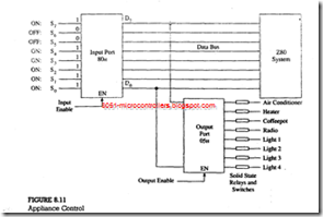
7. Write instructions to read the input port 80H and output the reading to the port 05H (see Figure 8.11). What appliances will be turned on with this output?
8. Write comments to explain the functions of the following instructions:
LD HL, 2065H
LD (HL), 00H
HALT
9. What are the contents of the accumulator after the execution of the instruction SUB A? Specify the status of the Z and CY flags.
10. Write the instructions to load FFH into the accumulator and increment A.
Specify the status of the S, Z, and CY flags after the execution of the increment instruction.
11. In the previous assignment (#10), replace the increment instruction with the instruction ADD A, 01H and explain how the flags S, Z, and CY are affected after the addition.
12. Specify the register contents and the flag status after the execution: of the following instructions. What is being displayed at OUTPRT?
13. Write instructions to load 40FFH into register HL and increment HL. Specify the contents of register HL.
14. Register HL contains 20FFH. What are the contents of register HL if the byte 01H is added (not incremented) to register L? What are the statuses of the S, Z, and CY flags after the addition?
15. Write instructions to perform the operations listed in 14, and assemble the code showing memory addresses.
16. Show the contents of the registers and the memory locations that are affected after the execution of the following instructions. Explain the difference between the two INC instructions shown below.
LDHL,209FH
LD(HL), FFH
INC (HL) INCHL
HALT
17. Find the results of the following operations and explain the difference between the two results.
|
SUB A |
SUBA |
|
LD HL,971FH |
LDHL,971FH |
|
LDBC,8F9CH |
LDBC,8F9CH |
|
ADDA,L |
ADDA,L |
|
ADDA,C |
ADDA,C |
|
ADDA,B |
SUB H |
|
SUB H |
ADDA,B |
|
HALT |
HALT |
18. Load 48A2H into register BC. Subtract the contents of C from B. If the answer is in 2’s complement, display 01H at PORT; otherwise, display the result. Assemble the code and execute the program.
19. Execute the program in 18 by loading F247H in register BC.
20. Three data bytes are stored in memory locations XX50, XX5l, and XX52H. Write instructions to subtract the bytes stored in memory locations XX50 and XX5l from the byte stored in location XX52H. If the answer is in 2’s complement, display FFH at PORT; otherwise, display the answer. Execute the instructions with the following set of data in Hex.
Set 1: XX50 = 32, XX51 = 78, XX52 = F9
Set 2: XX50 = 67, XX51 = 98, XX52 = F9
21. The Relative Jump instruction JR NZ, 68H is stored in memory locations XXA7H and XXA8H. Calculate the jump location.
22. If the opcode of the Relative Jump instruction JR NC, 8FH is located at memory location XX50H, calculate the jump location.
23. Assemble the code in Illustrative Program 1 (Section 8.6.3) and replace the instruction JP NZ, NEXT with the appropriate Relative Jump instruction and offset.
24. In Illustrative Program 2 (Figure 8. 10), assemble the code and replace the Jump instructions JP NC, SKIPCY; and JP NZ, NXTBYT with the appropriate Relative Jump instructions and their offsets.
