6.3 HOW TO WRITE, ASSEMBLE, AND EXECUTE A SIMPLE ASSEMBLY LANGUAGE PROGRAM
An assembly language program is a sequence of instructions written in mnemonics to perform a specific task. These instructions are selected from the instruction set of the microprocessor being used. To write a program, we need to divide a given problem into small steps and translate these steps into the operations the Z80 can perform. For example, the Z80 does not have an instruction that can multiply two’ binary numbers, but it can add. Therefore, the multiplication problem can be written as a series of additions.
After writing the instructions in mnemonics, you should translate them in to binary machine code; this process of translation is called assembling the code Quite often, this process involves intermediate steps, such as translating mnemonics into Hex code and then into binary code. The code assembly can be done manually, as described in this chapter, or using an assembler (a program that translates mnemonics into machine code), as described In the next chapter.
To execute a program, the binary code should be entered and stored in the R/W memory of a microcomputer so that the microprocessor can read and execute the binary instructions written in memory. In a single-board microcomputer the instructions are, generally, entered using a Hex keyboard. This is one of the reasons why we translate mnemonics into Hex code as an intermediate step rather than into binary code directly. When the Hex code is entered, the keyboard program, residing in the microcomputer system, translates the Hex code into binary code. The steps required to write, assemble, and execute a program are illustrated in the next section.
6.3.1 illustrative Program: Adding Two Hexadecimal Numbers PROBLEM STATEMENT
Write instructions to load the two hexadecimal numbers 32H and A2H into registers B and C, respectively. Add the numbers, and display the sum at the LED output port PORT 1.
PROBLEM ANALYSIS
Even though this is a simple problem, it is necessary to divide the problem into small steps in order to examine the process of writing programs. The wording of the problem provides sufficient clues for the necessary steps. They are as follows:
1. Load the numbers into the registers.
2. Add the numbers.
3. Display the sum at the output port PORT1.
FLOWCHART
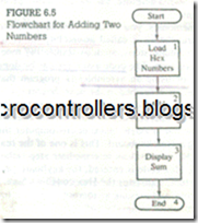
The steps listed in the problem analysis anti the sequence can be represented in a block diagram, called a flowchart. Figure 6.5 shows such a flowchart representing those steps. This is a simple flowchart, and the steps are self-explanatory. We will discuss flowcharting in the next section.
ASSEMBLY LANGUAGE PROGRAM
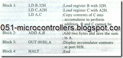
To write an assembly language program, we need to translate the blocks shown in the flowchart into Z80 operations and then into mnemonics. By examining the blocks in Figure 6.5, we can classify them into three types of Z80 operations: Block1and 3 are copy operations, Block 2 is an arithmetic operation, and Block
4 is a machine control operation. The translation of each block into mnemonics with comments is shown below.
FROM ASSEMBLY LANGUAGE TO HEX CODE
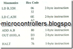
To convert the mnemonics into Hex code, we need to look up the code in the Z80 instruction set; this is called either manual or hand assembly. The Hex code is as follows:
STORING IN MEMORY AND CONVERTING FROM HEX CODE TO BINARY CODE
To store the program in R/W memory of a single-board microcomputer and display the output, we need to know the memory addresses and the output port address. Let us assume that R/W memory ranges from 2000H to 20FFH, and the system has an LED output port with the address 01H. To enter the program, the following steps are necessary:
1. Reset the system by pushing the RESET key.
2. Using Hex keys, enter the first memory address at which the program should be stored. Let us assume it is 2000H.
3. Enter each machine code by pushing Hex keys. For example, to enter the first machine code push 0, 6, and STORE keys. (The STORE key may be labelled differently in different systems.) When you push the STORE key, the program will store the machine code in memory location 2000H and upgrade the memory address to 2001H•
4. Repeat Step 3 until the last machine code 76H•
5. Reset the system.
Now the question is: How does the Hex code get converted into binary code? The answer lies with the Monitor program stored in the Read-Only Memory (or EPROM) of the microcomputer system. An important function of the Monitor program is to check the keys and convert Hex code into binary code. The entire process of manual assembly is shown in Figure 6.6.
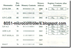
In this illustrative example, the program will be stored in memory as shown:
This program has nine machine codes and will require nine memory locations to store the program. The critical concept to be emphasized here is that the microprocessor can understand and execute only the binary instructions (or data); everything else (mnemonics, Hex code, comments) are for the convenience of those who write and use the assembly language programs.
EXECUTING THE PROGRAM
To execute the program, we need to tell the microprocessor where the program begins by entering the memory address 2000H• Then, we can push the Execute key (or the key with a similar label) to begin the execution. As soon as the Execute function key is pushed, Z80 loads 2000H into the program counter, and the program control is transferred from the Monitor program to our program.
The microprocessor begins to read one machine code at a time, and when it fetches the complete instruction, it executes that instruction. For example, it will fetch the machine codes stored in memory locations 2000H and 2001H and execute the instruction LD B, 32H; thus, it loads 32H in register B as shown above in the last column of Register Contents. Next, it loads A2H into register C and copies A2H from register C into the accumulator A. It should be emphasized that the contents of register C are not changed in the copying process. When the ADD instruction is executed, the contents of A are changed to D4H, which is the sum of 32H and A2H• It continues to execute instructions until it fetches the HALT instruction.
6.3.2 Program Documentation or Writing Format
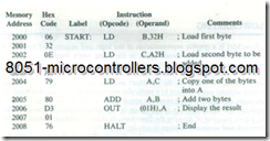
Program documentation is an important aspect of writing programs. The documentation should be able to communicate what the program does and the logic underlying the program, so that it can be debugged and modified if necessary. For our illustrative program, a writing format based on assembler files (discussed in the next chapter) is shown here.
This writing format has five columns: Memory Address, Hex Code, Label, Instruction (Opcode and Operand), and Comments. Each column is described below in the context of a single-board computer.
Memory Addresses These are 16-bit addresses of the system’s R/W memory in which the binary code of the user program is stored. In the illustration, we assumed that the R/W memory in our system begins at the address 2000H, and we chose to store the program starting at the location 2000H; we could have chosen any other available memory block to store our program.
Hex Codes These are the hexadecimal codes of the Z80 mnemonics we looked up in the instruction set; they were entered in memory using the Hex keyboard of the single-board microcomputer system. The key monitor program of the system translates these Hex codes and stores the binary equivalents in the proper memory locations.
Labels They are used to identify a memory location. The program has one label:
START. This label is used for documentation; it indicates the beginning of the program. The labels are used to identify memory locations and will be especially useful for Jump instructions when we use assemblers to write programs (discussed in the next chapter).
Instructions These are the Z80 mnemonics representing the microprocessor operations. Each instruction is divided into two parts: opcode and operand.
Comments The comments are written as a part of the proper documentation of a program to explain or elaborate the purpose of the instruction used. They thus play a critical role in the user’s understanding of the logic behind a program. Because the i1lustrative program is very simple, the comments shown are either redundant or trivial, but in general comments should not merely describe the meaning of mnemonics.
