Installation and Operation of Gas-Fired Water Heaters
The installation and operation of a gas-fired automatic storage water heater involves little possibility of error if the instructions of the manufacturer are strictly followed and due consideration is given to the following factors:
1. Location
2. Venting regulations
3. Water heater venting system
4. Size of flue pipe
5. Runs of flue pipe
6. Gas meter
7. Gas supply line
8. Hot-water circulation methods
9. Safety relief valves
10. Building and safety code provisions
11. Lighting and operating instructions
Location
The heater should be located at a point convenient to the flue or chimney and, if possible, at a point approximately equidistant from all hot-water outlets.
Venting Regulations
Many building codes prohibit connecting appliances to a common
flue or chimney with coal- or oil-fired equipment. Where regula- tions do not require venting of gas-fired equipment to a separate flue and it is vented to a common flue with coal- or oil-fired units, the flue pipe of the gas-fired water heater or other appliance should be connected to the chimney at a point above the flue pipe from the coal- or oil-fired equipment.
When possible, a separate hole in the chimney should be used for the water heater flue. If this is not possible, join the flue from the water heater and the flue from the heating boiler (or furnace) with a Y connection (never a T connection) and install a separate draft regulator for each unit.
When the chimney cannot handle the combined input of both the water heater and the heating plant, wire the two so that they do not operate simultaneously.
Water Heater Venting Systems
The venting system of a fuel-fired water heater is designed to transfer the products of combustion to the outdoors. By transfer- ring these potentially harmful gases outside the structure, the living spaces are maintained free of any possible air contamination. Electric water heaters do not require venting systems.
A typical venting system for a fuel-fired water heater consists of the following basic components:
1. Heater flues or heat exchangers
2. Draft diverter
3. Vent pipe connections
The design and arrangement of a venting system should take advantage of the natural tendency of hot gases to rise. These flue gases are a waste by-product of the combustion process. Because they are hot gases, they are lighter than the surrounding ambient air, and they tend to rise in a vertical path. The venting system should provide essentially a vertical path to take advantage of this natural vertical flow of the gases. The vent pipes should be of sufficient diameter to carry the volume of gas without restricting its natural flow rate.
Excessive cooling of the flue gases can be avoided by providing a controlled mixture of dilutant air from the draft diverter. If the flue gases cool, condensation will occur, the gases will grow heavier, and it will be impossible to maintain draft. The same condition (that is, excessive cooling) will occur if the vents are unusually long or high. This can be minimized by insulating the vent pipes.
Fans are used on some high-input water heaters to supplement natural venting. The use of a fan is sometimes referred to as power venting, and the water heaters are referred to as power-vent water heaters. In most cases where a fan is used, proper venting can generally be obtained from a smaller-diameter vent pipe. However, some provision should be made to automatically shut off the water heater in case of a fan failure. Fan-assisted venting allows the use of much longer horizontal or vertical flue pipes than would ordinarily be the case. As a result, the water heater can be located anywhere in the structure. On the downside, the fan and water heater are electrically operated, and a power failure will shut down the unit.
Vent pipe connections are often made directly to the outdoors or through a chimney wall. When direct venting is the case, the vent pipe connects to a vent outlet hood.
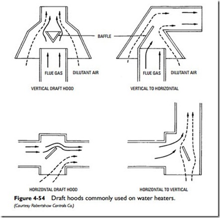
Draft hoods are used on all water heaters that rely on natural vent action to eliminate contaminating flue gases. The draft hood should contain an inlet and outlet opening for the flue gases, and an air dilutant intake and relief opening to relieve downdraft conditions.
A well-designed draft hood should be able to prevent excessive updraft in the burner compartment and momentary excessive downdraft conditions. Sometimes the flow rate of flue gases suddenly increases and results in an excessive updraft condition in the burner compartment. The amount of air flowing into the flue through the air dilutant intake is clearly insufficient to control the condition. The diverter should be designed to allow an increase in air intake during excessive updraft conditions so that the weight of the flue gases is increased and the flow rate slowed.
When downdraft conditions occur, the baffles and relief opening in the draft hood allow the downdraft to be relieved outside the flue so that the burner flame is unaffected. This expulsion of the comustion by-products through the air intake is only a momentary condition.
Size of Flue Pipe
The size of the flue pipe should not be less than that specified by the manufacturer or that shown in available tables for the rated gas input.
Flue Pipe Run
Horizontal runs of the flue pipe should pitch upward toward the chimney connection and should run as directly as possible, avoid- ing unnecessary bends or elbows. The backdraft diverter supplied by the manufacturer or other approved draft hood of adequate size should be employed.
Gas Meter
The gas meter must be of adequate size or capacity to supply not only the requirements of the water heater but also the requirements of all other gas-fired equipment.
Gas Supply Line
The gas supply line to the water heater should be adequate in size to supply the full rated gas input of the heater at the available pressure, taking into consideration the pressure drop through the supply line. A separate gas supply line from the meter to the water heater should be employed if the existing line from the meter is too small to supply the combined requirements of the water heater and other equipment or appliances that may be connected to it.
Safety Relief Valves
Both a pressure relief valve and a temperature relief valve are used to ensure the safe operation of a water heater. The operating char- acteristics of these two safety relief valves have already been described (see Safety Relief Valves in this chapter).

