Combination Gas Valve
A combination gas valve (or combination gas control) combines in a single unit all the automatic and manual control functions necessary to govern the operation of a gas-fired water heater.
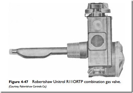
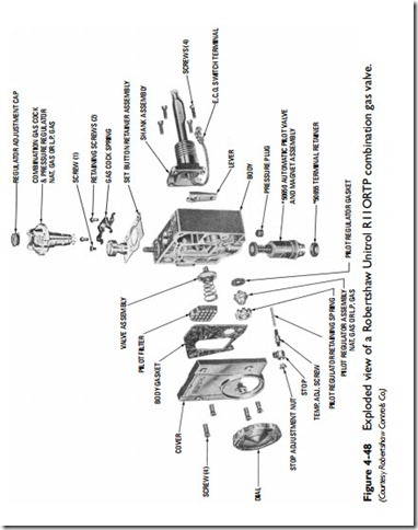
A typical combination gas valve is shown in Figures 4-47 and 4-48. This particular unit contains a water heater thermostat (thermostatic valve), automatic pilot valve, automatic gas shutoff device, main gas–pressure regulator, pilot gas–pressure regulator, and manual valve (gas cock).
The installation instructions included with most combination gas valves are usually very complete and should cover the following points:
1. Disassembly and assembly instructions
2. Automatic shutoff valve and magnet replacement
3. Gas-cock lubrication
4. Thermostatic valve cleaning instructions
5. Pressure-regulator adjustment
6. Thermostat calibration
7. Lighting procedure
8. Test procedure
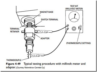
Most control manufacturers provide test kits to test the opera- tion of the thermocouple, thermomagnet, and automatic safety shutoff device. The test kit consists of a millivolt meter and an adapter for testing the thermomagnet (see Figure 4-49).
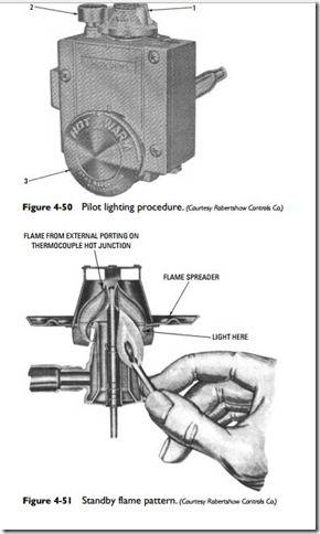
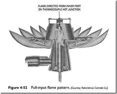
As shown in Figure 4-50, the manual valve (gas cock) is used when lighting the pilot. The gas-cock dial (1) is turned to the off position and at least 5 minutes is allowed to pass. This should be sufficient time for any gas that has accumulated in the burner com- partment to escape. The gas-cock dial is then turned to the start position, and the set button (2) is depressed while the burner is being lit (see Figure 4-51). The standby flame is allowed to burn for approximately 1⁄2 minute before the reset button is released (see Figure 4-52). Unless there is a problem, the burner should stay lit after the reset button has been released. After releasing the reset button, turn the gas-cock dial to the on position and turn the tem- perature dial (3) to the desired setting.
The combination valve shown in Figure 4-53 does not use a reset button in the lighting procedure. The upper dial is turned counter- clockwise to the pilot position and held against the spring-loaded stop until the pilot burner lights. After the pilot burner burns for about 30 to 60 seconds, the upper dial is turned clockwise to on for automatic control. The lower dial is then set for the desired water temperature.
