A heat pump is a refrigeration device used to transfer heat from one room or space to another. The heat pump is designed to take heat from a medium-temperature source, such as outdoor air, and convert it to higher-temperature heat for distribution within a structure. By means of a specifically designed reversing valve, the heat pump can also extract heat from the indoor air and expel it outdoors.
Because a heat pump system uses the reverse-cycle principle of operation, its operating principle is sometimes referred to as reverse- cycle conditioning or reverse-cycle refrigeration. The latter term is not correct because there are fundamental differences between the operating principles of a heat pump and a true refrigeration unit. The confusion probably stems from the fact that during the cooling cycle, the operation of a heat pump is identical to that of the mechanical refrigeration cycle in a packaged air-conditioning unit. The indoor coil functions as an evaporator, cooling the indoor air. The outdoor coil is a condenser, in which the hot refrigerant gas releases heat to the outside air.
Heat Pump Operating Principles
The two principal phases of heat pump operation are the heating and cooling cycles. A third phase, the defrost cycle, is used to protect the coils from excessive frost buildup.
Heating Cycle
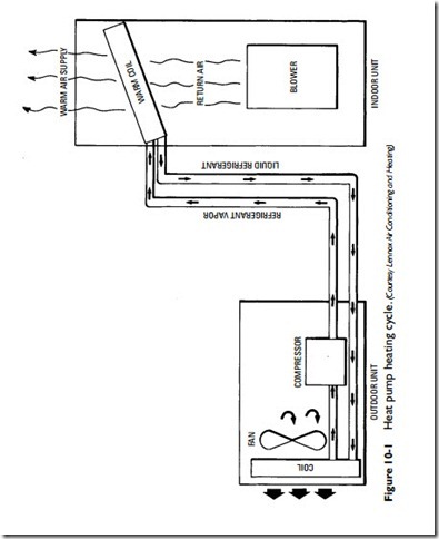
The heating cycle of a heat pump begins with the circulation of a refrigerant through the outdoor coils (see Figure 10-1). Initially, the refrigerant is in a low-pressure, low-temperature liquid state, but it soon absorbs enough heat from the outdoor air to raise its temper- ature to the boiling point. Upon reaching the boiling point, the refrigerant changes into a hot vapor or gas. This gas is then com- pressed by the compressor and circulated under higher pressure and temperature through the indoor coils, where it comes into contact with the cooler room air that circulates around the coils. The cooler air causes the gas to cool, condense, and return to the liquid state. The condensation of the refrigerant vapor releases heat to the interior of the structure. After the refrigerant has returned to a liquid state, it passes through a special pressure-reducing device (an
expansion valve) and then back through the outdoor coils where the heating cycle begins all over again. The temperature of the room air that originally cooled the higher-temperature refrigerant vapor is itself increased by the process of heat transfer and recirculated throughout the room to provide the necessary heat.
Note
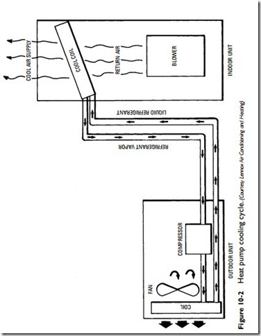
A heat pump is designed to reverse the action or direction of heat transfer depending on whether heating or cooling is desired. As a result, the indoor and outdoor coils change their functions based on the heating or cooling cycle. The outdoor coil becomes the condenser in the cooling cycle and the evaporator in the heating cycle.The indoor coil, on the other hand, becomes the evaporator in the cooling cycle and the condenser coil in the heating cycle.
Cooling Cycle
In the cooling cycle, the reversing valve causes the flow of the refrigerant to be reversed. As a result, the compressor pumps the refrigerant in the opposite direction so that the coils that heat the building or space in cold weather cool it in warm weather. In other words, the heat is extracted from the interior, cycled through the heat pump, and then expelled outside the building or space during the condensation of the refrigerant (that is, its change from a gaseous to a liquid state) (see Figure 10-2).
Heat Sink
The heat given off by the process of condensation is received by the heat sink. This is true for both the heating and cooling cycles. In the former, the air of the rooms or spaces functions as the heat sink. In the cooling cycle, the outside air, a water source (for example, a well, a pond, or a sewage pipe) or the ground commonly serve as heat sinks outside the structure.
Defrost Cycle
Because the outdoor air is relatively cool when the heat pump is on the heating cycle, and the outdoor coil is acting as an evaporator, frost forms on the surface of the coil under certain conditions of temperature and relative humidity. Because this layer of frost on the coils interferes with the efficient operation of the heat pump, it must be removed. This is accomplished by putting the heat pump through a defrost cycle.
In the defrost cycle, the action of the heat pump is reversed at certain intervals and returned to the cooling cycle. This is done to
temporarily heat the outdoor coil and melt the frost accumulation. The temperature rise of the outdoor coil is hastened because the operation of the outdoor fan stops when the system switches over to the cooling cycle.
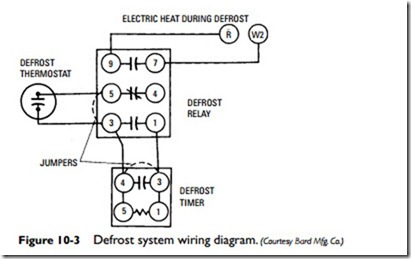
The system will remain in the cooling cycle until the coil temperature has risen to 57°F. The time of the defrost cycle will vary, depending on how much frost has collected on the coil. During this period, the indoor motor continues to operate and blow cool air. This cold condition can be eliminated by installing an electric heating element (see Auxiliary Electric Heating Elements in this chapter). The heating element is wired in conjunction with the second stage of a two-stage thermostat and will come on automatically when the heat pump is in the defrost cycle (terminals 9 and 7 on the defrost relay in Figure 10-3).
The defrost cycle control system consists of a thermostat, timer, and relay. The defrost thermostat is located at the bottom of the out- door coil where it can respond to temperature changes in the coil. It makes contact (closes) when the temperature of the outdoor coil drops to 32°F. This action of the thermostat causes the timer motor (located in the unit electrical box) to start. After the accumulative running periods reach either 30 minutes or 90 minutes (depending on the type of cam installed in the timer), the timer energizes the defrost relays, which reverses the reversing valve and stops the out- door fan motor. The unit remains in the defrost cycle (cooling cycle) until the temperature of the outdoor coil reaches 57°F. At that temperature the coil is free of frost and the frost thermostat opens to
stop the timer and return the unit to the heating cycle. The timer will not run again until the outdoor coil temperature drops to 32°F. The timer runs only when the thermostat contacts are closed.
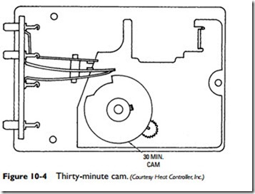
A defrost timer is shipped with a 30-minute cam installed (see Figure 10-4). With this cam, the unit will defrost once every 30 minutes (of accumulated running time) when the outdoor coil tem- perature is below 32°F. If there is little or no frost on the coil, the defrost cycle will be correspondingly short (approximately 45 seconds to 1 minute). A 90-minute cam is recommended.


