WARM-AIR FURNACES
The warm-air furnace is a self-contained heating unit designed to supply warm air to the interior of a structure. Warm-air furnaces used in central heating systems usually employ a system of ducts to distribute the air to the various rooms and spaces within the structure.
These furnaces can be classified according to the method of air circulation into the following two basic categories: ( 1) gravity warm-air furnaces and (2) forced warm-air furnaces. A distinct advantage of the forced warm-air furnace is that its blower can move the air in any direction. As a result, this type of furnace can be located anywhere in the structure. Furthermore, the ducts do not have .to be located above the heating unit as is the case with gravity warm-air furnaces. These advantages of the forced warm air furnace have contributed to its tremendous popularity over gravity type furnaces. Both of these types are described in con siderable detail in Chapter 10 (FURNACE FUNDAMENTALS).
Other criteria used for classifying warm-air furnaces include:
(1) the type of fuel used (e.g. gas, oil, coal, or electricity); (2) the method of air distribution (ducts or pipeless), and ( 3) the method of firing (automatic or manual). Specific chapters in this book deal individually with some of these criteria (e.g. see Chapter 11. GAS-FIRED FURNACES; Chapter 12. OIL-FIRED FURNACES, etc.).
CONTROL COMPONENTS
The types of controls used in a warm-air heating system will depend upon a number of factors, including: ( 1) the method of air circulation used (e.g. forced or gravity); (2) the size of the structure; (3) the method used for supplying the fuel (automatic or manual) to the fire; and so on. In other words, a control system is for all intents and purposes custom designed to fullfill the requirements of a specific heating system.
All gravity and forced warm-air furnaces in central heating systems are controlled by a thermostat located in one of the rooms. If the heating system is zoned, two or more room thermo stats will be used. In forced warm-air sys,tems equipped with automatic burners or stokers, the thermostat will also control the operation of these units.
Each furnace should be equipped with a high-limit control to shut off the air or gas burner when plenum air temperatures exceed the furnace manufacturer’s design limits. The high-limit control is automatic and will switch on the burner again as soon as the air temperature in the plenum has returned to normal (i.e. reached a level below the manufacturer’s design limits). The high-limit control is frequently designed to operate in conjunction with the fan (blower) swi,tch in forced warm-air furnaces.
Other types of controls used in warm-air heating systems are described in Chapter 4 (THERMOSTATS AND HUMIDI STATS); Chapter 5 (GAS AND OIL CONTROLS); and Chap ter 6 (OTHER AUTOMATIC CONTROLS) of Volume 2.
DUCTS AND DUCT SIZING
Ducts are passageways used for conveying air from a furnace or cooling unit to the rooms and spaces within a structure. The ductwork is also used to return ·the air to its source for recirculation.
The air is distributed to the rooms or spaces by means of grilles, registers, and diffusers. The size and location of ,the supply air outlets and the return air inlets are determined by such design factors as: (1) use (heating or cooling), (2) air velocity, (3) throw, ( 4) drop, and (5) the desired distribution pattern.
These and other aspects of air outlet and air inlet design and selection are considered more thoroughly in Chapter 7, Volume 2 (DUCTS AND DUCT SYSTEMS).
Designing and sizing a duct system is a compromise between the requirements and limitations of both the structure and the heating and cooling system. Duct sizing will be affected by a number of variables, including: ( 1) the architectural design of the structure, ( 2) space limitations, ( 3) the required air supply, (4) the allowable duct air velocities, (5) the desired noise level, and ( 6) the capacity of the blower. Adequately sized ducts rep resent the best possible compromise among these variables.
Accuracy in estimating the resistance to the flow of air through the duct system is important in the selection of blowers for appli cation to such systems. Resistance should be kept as low as pos sible in the interest of economy. However, underestimating the resistance will result in failure of the blower to deliver the required volume of air. The various calculation methods used for sizing ducts are given in Chapter 23 (DUCTS AND DUCT SYSTEMS). ducts are given in Chapter 7, Volume 2 (DUCTS AND DUCT SYSTEMS).
A number of precautions should be taken in the design of a duct system. For example, careful study should be made of the building drawings with consideration being given to the construc tion of duct locations and clearances. Other recommendations that should be considered when designing a duct system can be sum marized as follows:
1. Keep all duct runs as short as possible bearing in mind that the air flow should be conducted as directly as pos sible between its source and delivery points, with the fewest possible changes in direction.
2. Select locations of duct outlets so as to insure proper air distribution.
3. Provide ducts with cross sectional areas which will permit air to flow at suitable velocities.
4. Design for moderate velocities in all ventilating work to avoid waste of power and to reduce noise.
COOLING WITH A WARM-AIR HEATING SYSTEM
The simplest method of cooling a house in the summer is to use the blower of a forced warm-air furnace. Most furnaces have a manual blower switch that can be used :to circulate the air.
If you plan to install a central air conditioning system capable of maintaining comfortable indoor temperatures during ·the warmer months, you must first examine the existing furnace and duct system and determine what changes (if any) must be made to handle the cooling load.
Forced warm-air furnaces can often be converted ·to year-round air conditioning by installing a cooling coil in the furnace supply duct and connecting it to a compact compressor-condenser unit located outdoors. The existing duct system may be inadequate for air conditioning, but this can be modified to handle the cool air by increasing the size of certain ducts or by installing additional ducts.
Some furnaces (particularly gravity warm-air furnaces) can not be fitted with cooling coils, but the existing ductwork is adequately sized for cooling. If this should be the case, the furnace can be bypassed with the cooling coils and air handling equipment installed in a short length of duct which feeds into the main supply and return-air ducts at a point near the furnace. Dampers must be placed in the ducts between the furnace and the cooling coil to prevent the warm and cool air from mixing.
If both the existing furnace and ductwork cannot be used, it will be necessary to install a separate and independent air con di,tioning system. Adding one or more window units is the most common method of accomplishing this. Slightly more expensive is the use of a <through-the-wall unit, which is installed by cutting a hole in the wall. The compressor-condenser section is located on the outside to reduce the noise level. Neither window unHs nor through-the-wall units use ductwork to distribute the cool air.
The most expensive separate and independent air conditioning systems are the single-package unit systems and the very popular split systems. Both use ductwork to distribute the cool air. A single-package unit system is limited to the installation of the cooling unit in the attic or basement, with the former location offering the fewest design problems. The advantage of a split system is that the cooling unit can be located anywhere inside the structure. In both systems, the preferred location of the compressor condenser section is outdoors.
AIR CLEANING
The air cleaning equipment used in forced warm-air heating and cooling systems commonly takes the form of washable or disposable air filters, or electronic air cleaners.
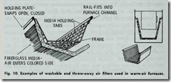
Washable and disposable air filters are ins,talled in the return air plenum of a forced warm-air furnace as shown in Fig. 10. These are dry-type filters consisting of cellulose fibers, steel wool. or some other suitable material set in a wire frame. These filters are effective only when dus:t concentrations are limited to 4 gr. per 1000 cubic feet of air or lower. Consequently, they are restricted in use to residences or small buildings. Air filters are not used in gravity warm-air heating systems, because they impede the rate of air flow.
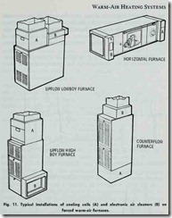
Electronic air cleaners are designed for return air duct installa tion at the furnace, air handler (in 1the duct) or air conditioning unit. They generally operate on the electrostatic precipitation prin ciple. and are capable of removing up to 95 per cent of all airborne particles (e.g. dust, tobacco, smoke, etc.). The dust particles are given an electric charge when they pass ·through an ionizing field, and are collected when they subsequently pass between collector plates having an opposite charge. Typical installations are illus trated in Fig. 11.
The various types of air filters and electronic air cleaners used in cleaning and filtering the air are described in Chapter 14, Volume 3 (AIR CLEANERS AND FILTERS).
HUMIDIFIERS AND DEHUMIDIFIERS
Air that has a very low level of humidity is too dry for com fort, and can cause damage to walls, interior woods, and furnish ings. This results from the fact that dry air will absorb moisture from other sources, including ·the human body. The moisture robbing effect of dry air is particularly noticeable on the sensitive nasal and throat membranes. Moisture can be added to the air by humidification, and the device used to add moisture is called a humidifier.
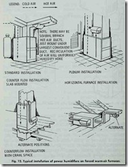
The humidifiers used in heating and cooling systems are de signed to maintain the relative humidity within the comfort zone. They are available in a number of different types, each based on a different operating principle. Pan-type humidifiers, for example, contain a reservoir of water which evaporates into the warm air flowing through ,the supply duct. The water level in the reservoir is controlled by a float control. The desired humidity level is determined by a humidity control setting. When the relative humidity drops below the humidity control setting, a humidifier fan is actuated and air is blown over the water in the reservoir. Moisture is then picked up by the air and blown into the space to be humidified. Other types of humidifiers are: ( 1) the spray-type air washer and (2) the steam-type humidifiers (either air or electrically operated). Typical humidifier installations are illus trated in Fig. 12.
Sometimes air will have a humidity level that is too high. The excess moisture resulting from this condition can also cause
damage to walls, interior woods, and furnishings, as well as prove very uncomfortable for the occupants. Excess moisture can be removed from ·the air, and the device used to remove .the moisture is called a dehumidifier.
Dehumidifiers operate either on the cooling or absorption method. The former method accomplishes dehumidification by an air washer with a water spray 1:emperature lower than the dew point of the air passing through the unit. Condensation occurs and both latent and sensible heat are removed.
In the absorption method of dehumidification, sorbent ma terials are used for removing moisture from the air. Air to be dehumidified is drawn or blown through a screened bed of dry solid absorbent and the water vapor in the air is caught and re tained in the pores of the absorbent.
Both humidifiers and dehumidifiers are described in greater detail in Chapter 13 of Volume 3.
ADVANTAGES OF A WARM-AIR HEATING SYSTEM
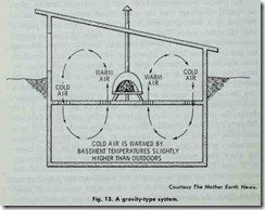
By present comfort standards, gravity warm-air heating offers no special advantage and too many disadvantages to be recom mended as a heating system in the types of structures popular with the public today. The architectural design of these s·tructures necessitates the use of a forced warm-air heating system. Because the gravity system lacks a blower, air circulation (and, therefore, heat distribution) depends upon the temperature difference be tween the rising warm air and the descending cold air. Unfortu nately, many of our houses and buildings are designed in such a way that a gravity system would require a considerable tempera ture difference to obtain the desired rate of air movement. If you design ·the structure around a gravity heating system, then quite different results are possible. For example, a residence buil·t by a gentleman named Wendell Thomas in western North Carolina contains a gravity-type heating system using a simple wood burn ing stove that produces indoor temperatures ranging between 60°F and 75°F year-round. The north and west sides of the structure were set into the ground. No windows were placed in the north wall, and the windows in the other walls were two or three panes thick. As shown in Fig. 13, the warm air heated by the stove rises and gives off its heat to the room. As it loses its heat, it cools and descends along the inside surfaces of .the exterior walls, passes through metal air vents in the floor, and then enters the basement where it is warmed somewhat by the slightly warmer indoor temperatures. It then rises through metal air vents placed in the floor around the stove where it is reheated and recirculated. Construction and operation details of this heating system can be obtained by sending ten cents and a self-adqressed envelope to THE MOTHER EARTH NEWS, BOX 957, DES MOINES, IOWA 50304. Ask for Reprint No. 39, “THE SELF-HEATING, SELF-COOLING HOUSE.”
In a structure designed to take into consideration the operating principles of a gravity-type heating system, the operating costs
will be lower than any other ,type system.
The advantages of a forced warm-air heating system are as follows:
1. The installation costs are lower than those for hot-water or steam heating systems.
2. Heat delivery is generally quicker than other systems.
3. Heat delivery can be shut off immediately.
4. Air cleaning and filtering can be cheaply and easily provided.
5. The humidity level of the air can be easily controlled.
6. Air conditioning can be added without great difficulty or cost.
7. The furnace (because of its blower) can be placed in a number of different locations in the structure.
DISADVANTAGES OF A WARM-AIR HEATING SYSTEM
One of the principal disadvantages of a gravity warm-air heat ing system is that the furnace must be centrally located at the lowest point in the S>tructure. This, of course, severely limits the design flexibility of the structure itself. Other disadvantages of gravity warm-air heating systems include:
1. Slow response to heat demand from the thermostat.
2. Slow air movement.
3. Air filtering is inadequate or nonexistent.
Forced warm-air heating systems depend upon blowers to circulate the air ,through a network of sheet metal ducts. Both the operation of the blower and the expansion and contraction of the ducts as the air temperature rises or falls can cause distracting noise .
Warm-air outlets can frequently create decor ating problems. In order to operate effectively, the registers should never be blocked by furniture or carpeting. This requirement, of course, restricts furniture arrangement and the placement of carpet.
The blower in a forced warm-air heating system will create a certain amount of air turbulence. This rapid agitation of the air causes dust particles to circulate and deposit on walls, furniture, and other surfaces. Ordinary filters will remove most of the larger particles, but are not very effective against smaller ones. An electronic air fiher is recommended for the latter.
Warm-air heating systems require separate hot water heaters to supply the hot water necessary for household use. This require ment for additional equipment adds to the initial installation costs for the system (in a hot-water heating system, the hot water for household use is supplied by the boiler).
Forced warm-air heating systems supply convected heat through forced air movement. The heat is supplied in bursts (rather than a continuous, sustained flow) when the room thermostat calls for it. This results in room temperatures varying up and down several degrees. The variation in temperature can be considerably reduced by setting the fan switch for continuous blower operation.


