Combination Fan and Limit Control
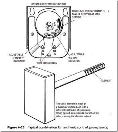
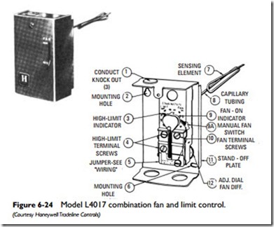
A combination fan and limit control combines the functions of a
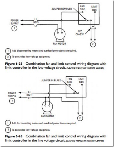
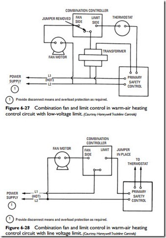
Combination controllers are wired in much the same way as the individual controls. Examples of some typical wiring hookups are shown in Figures 6-25, 6-26, 6-27, and 6-28. These combined controls can be used in line voltage, low-voltage, or self-energizing millivolt systems.
The combination fan and limit controller should be located where it will provide the best possible operating characteristics.
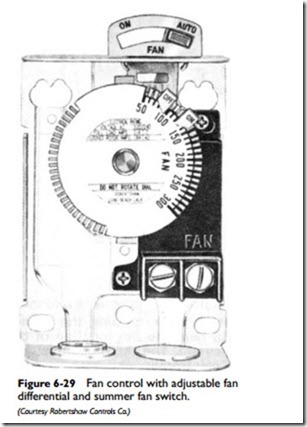
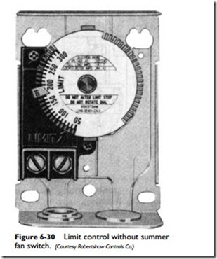
Limit switch terminals are on the left side of the control, fan switch terminals on the right. This arrangement is true of combination fan and limit controls as well as single-purpose types (see Figures 6-29, 6-30, 6-31, and 6-32).
On the fan and limit controls shown in Figures 6-29, 6-30, 6-31, and 6-32, temperature settings can be changed by moving the temperature-setting pointers. Temperature settings are interlocked to prevent the limit off from being set as low as the fan on pointer. Sometimes the limit off setting will be factory-locked to a specific setting. If this is the case, do not attempt to adjust this setting. A safety interlock prevents the fan on pointer from being set as high as the limit off pointer.
Some combination fan and limit controls are equipped with a manual summer fan switch to provide continuous fan operation for summer ventilation. To operate the blower during summer weather without the burner in operation, move the switch lever on the manual summer fan switch from auto to on position. This will provide continuous fan operation until the lever is moved to the auto position.
As shown in Figure 6-33, the metal tabs on the temperature dial of the Robertshaw combination fan and limit controller can be bent back to serve as stops for the fan and limit setting pointers. The dial is held to prevent rotation, and the pointer is pressed in and rotates to the proper temperature setting. The first tab above the pointer is bent back 90ºtoward the sensing element.
A certain amount of caution must be exercised when installing a combination fan and limit control. These controls can be either located in the furnace plenum or mounted directly on a panel, but the sensing element must be located in the path of free-flowing air. Never mount the control near the cool-air intake, and keep the
sensing element away from any hot metal surfaces. Furthermore, make sure you mount the control where it is accessible for making temperature adjustments.
