STARTING METHODS FOR SQUIRREL-CAGE MOTORS
There are several methods that can be employed to start three-phase squirrel-cage motors. These methods include:
1. Across-the-line starting.
2. Resistor/reactor starting.
3. Autotransformer starting.
4. Wye-delta starting.
5. Part winding starting.
Across-the-Line Starting
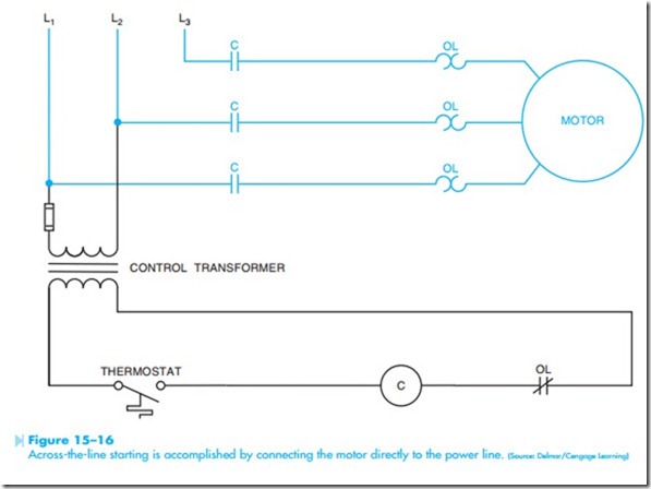
The simplest of these methods is across-the-line starting. Across-the-line starting is accomplished by connecting the motor directly to the power line, Figure 15–16. This method of starting is used when the inrush current, called locked rotor current, is not so great as to adversely affect the power line. Across-the-line starting is employed for all small horsepower motors, and depending on the local power base, may be used for motors of several hundred horsepower.
Resistor/Reactor Starting
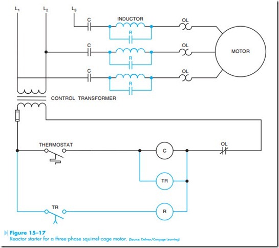
Often it is necessary to reduce the inrush current during the starting period of large motors. One method of reducing the starting current is to connect resistors or reactors (choke coils or inductors) in series with the motor during the starting period, Figure 15–17. This permits the resistance of the resistors or the inductive reactance of the reactors to limit the inrush current when the motor is first started. After the motor has accelerated to near full
load speed, the resistors or reactors are shunted out of the circuit. Several methods may be employed for shunting the resistors or reactors out of the line. The circuit shown in Figure 15–17 uses a time delay relay to energize R contactor after some period of time. The circuit operates as follows:
• When the thermostat contact closes, the coils of the compressor contactor (C) and the on-delay timer (TR) energize.
• When the compressor contactor energizes, C contacts close and connect the motor and reactors to the power line.
• After some period of time, timed contact TR closes and energizes the R contactor causing the R contacts connected in parallel with the current limiting inductors to close and shunt the inductors out of the line. The motor is now connected to full voltage.
Autotransformer Starting
Autotransformer starting differs from resistor or reactor starting by decreasing the voltage applied to the motor during the starting period instead of inserting resistance or inductive reactance in series with the motor. It should be noted that when the voltage to the motor is reduced, the torque is reduced also. A 50% reduction of voltage will pro- duce a 50% reduction of current also, but the torque is reduced to 25% of the value produced by full volt- age starting.
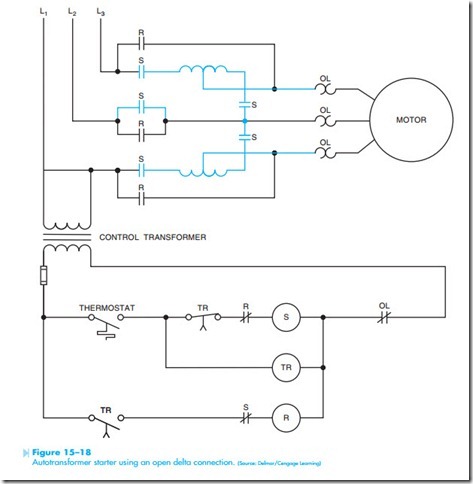
Several methods can be employed when using autotransformer starting. Some starters used three transformers, but most use two transformers con- nected in an open delta, Figure 15–18. In this circuit, notice the addition of the normally closed R contact connected in series with S coil and the
normally closed S contact connected in series with the R coil. This is referred to as interlocking. Interlocking is used to prevent one contactor being energized while some other contactor is energized. In this circuit, coils R and S can never be energized at the same time. The circuit operates as follows: (It will be assumed that timer TR is set for a delay of 3 seconds).
• When the thermostat contact closes, coils S and TR energize.
• All S contacts change position. The normally open S contacts close and connect the autotrans- former to the line. The motor is now connected to reduced voltage. The normally closed S contact connected in series with the coil of the R contactor opens and prevents the possibility of the R coil being energized.
• After a delay of 3 seconds, the TR timed contacts change position.
• The normally closed TR contact connected in series with the S coil opens and disconnects it from the line.
• When the S coil deenergizes, all S contacts return to their normal position. The autotransformer is now disconnected from the line and the contact connected is series with R coil is now closed.
• When the normally open TR contact closes, the R coil energizes and all R contacts change position.
• The normally open R contacts close and connect the motor directly to the power line. The normally closed R contact opens and prevents the possibility of S coil being energized at the same time.
Wye-Delta Starting
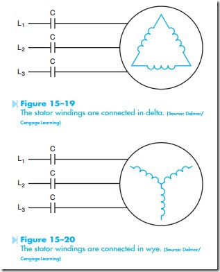
Wye-delta starting is also known as star-delta starting. Wye-delta starting is used to reduce the inrush current during the starting period by connecting the stator windings of the motor in a wye configuration during the starting period and then reconnecting them in delta during the run period. If the stator windings are connected in wye, the inrush cur- rent will be one-third the value it would be if they were connected in delta. Assume that the motor stator windings have an impedance of 2.5 ohms each. Now assume that the windings are connected in delta, Figure 15–19. It will also be assumed that the motor is connected to a line voltage of 480 volts. In a delta connection, the phase voltage is the same as the line voltage. Therefore, when the C contacts close, 480 volts will be applied across 2.5 ohms. This will produce a current in each phase of 192 amperes.
by a factor of the square root of 3 (1.732). There- fore, 277 volts is applied across each stator winding instead of 480 volts (480/1.732). This produces a phase current of 110.8 amperes. Because the stator windings are now connected in wye instead of delta, the line current is the same as the phase current. The motor inrush current has been reduced from amperes to 110.8 amperes by reconnecting the stator windings from delta to wye.
There are two conditions that must be met when wye-delta starting is to be used.
1. The motor must be designed to operate with its stator windings connected in delta during the normal run period.
2. All stator winding leads must be accessible In a delta connection, the line current is greater than the phase current by a factor of the square root of 3 (1.732). Therefore, the line current supplied to the motor is 332.5 amperes (192 x 1.732).
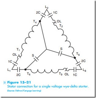
Another consideration when using wye-delta start- ing is that the overload heaters should be sized for the phase current value and not the line current value. The basic stator connection for wye-delta starting is shown in Figure 15–21. Notice that the overload heaters are connected in the phase wind- ings not in the line leads.
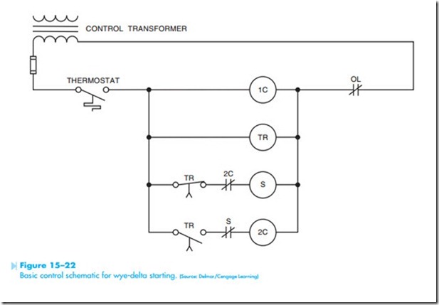
A basic control schematic for a wye-delta starter is shown in Figure 15–22. To understand the operation of this circuit assume that timer TR has been set for a delay of 3 seconds.
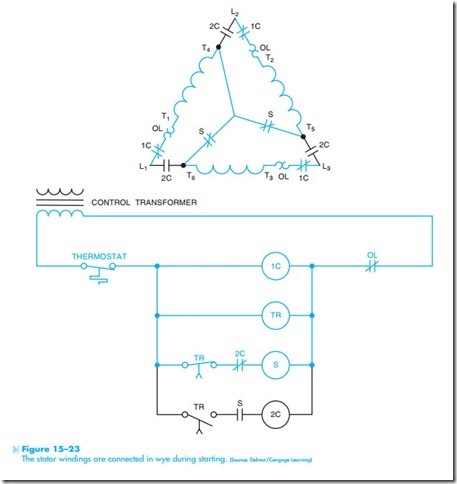
• When the thermostat contact closes, a current path exists through coils 1C, TR, and S, Figure 15–23.
• The 1C load contacts close to supply power to the motor T leads.
• The S contacts change position also. The two S load contacts close and connect the stator winding in a wye configuration by shorting T4, T5, and T6 together. The normally open S contact connected in series with coil 2C opens to provide interlocking protection.
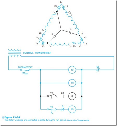
• After a delay of 3 seconds, both TR contacts change position, Figure 15–24.
• The normally closed TR contact connected in series with S coil opens and deenergizes S contactor causing all S contacts to return to their normal position. The normally closed S contact connected in series with coil 2C recloses to provide a current path to coil 2C.
• When the normally open TR contact connected in series with coil 2C closes, coil 2C energizes causing all 2C contacts to change position. The 2C load contacts close and reconnect the motor stator windings in a delta configuration. The normally closed 2C contact connected in series with S coil opens to provide interlocking protection.
Part Winding Starters
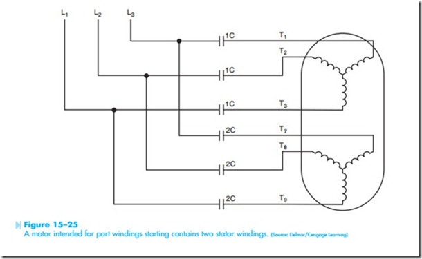
Another method for reducing the starting current of large three-phase squirrel-cage motors is part winding starting. Motors intended for use with part winding starting contains two separate stator windings, Figure 15–25. Each winding is rated for
the intended line voltage. The impedance of a single stator winding is double that of the two windings connected in parallel. Dual voltage motors can also be used for part winding starting provided the line voltage corresponds to the low voltage rating of the motor. A 480/240-volt motor could employ part winding starting provided the motor is connected to 240 volts and not 480 volts. In this situation T4, T5, and T6 are connected and power is connected to T1, T2, and T3 during the starting period. After some period of time, power is also connected to T7, T8, and T9. This has the same effect as connecting the stator windings in parallel.
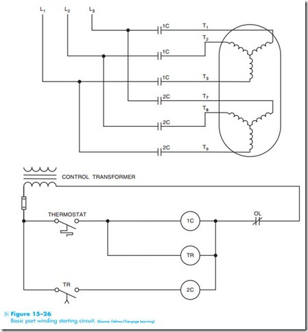
A basic circuit for part winding starting is shown in Figure 15–26. To understand the operation of the circuit, assume that timer TR has been set for a delay of 3 seconds.
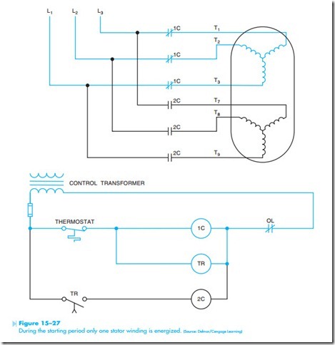
• When the thermostat contact closes power is provided to coils C1 and TR, Figure 15–27. All 1C contacts close and connect T1, T2, and T3 to the power line.
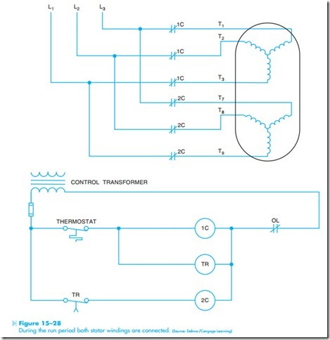
• After a delay of 3 seconds, the normally open TR contact connected in series with 2C closes and energizes coil 2C, Figure 15–28.
• When the 2C load contacts close, power is connected to T7, T8, and T9. This has the same effect as connecting the two windings in parallel.
