Installing Steam Traps
The installation of steam traps requires the following modifications in the piping:
1. Install a long vertical drip and a strainer between the trap and the apparatus it drains. The vertical drip should be as long as the installation design will permit. Exception: Thermostatic traps in radiators, convectors, and pipe coils are attached directly to the unit without a strainer.
2. A gate valve should be installed on each side of a trap, along with a valved bypass around the traps if continuous service is required. This permits removal of the trap for servicing, repair, or replacement without interrupting service.
3. A check valve and gate valve should be installed on the dis- charge side of a trap used to discharge condensation against back pressure or to a main located above the trap (as for lift service).
Always carefully follow the steam trap manufacturer’s instructions for installing a steam trap. If these instructions are not available, call the factory or an authorized representative for information before attempting to install the trap. The following are offered as guidelines for installing steam traps:
1. All work must be performed by qualified personnel trained in the correct installation of the trap.
2. Installation work must comply with all local codes and ordinances.
3. Allow the boiler to cool down to approximately 80˚F and the pressure to drop to 0 before attempting to do any work on the trap.
4. Wear heat-resistant gloves to prevent serious burns when opening and shutting steam valves.
5. Cap off the gate valves if they are not connected to a drain or not in use for test or pressure-relief purposes to prevent property damage, serious injury, or death.
6. Connect a temporary pipe between the steam pipe opening and a drain to prevent injury from steam pipe blow-down. In lieu of installing a temporary pipe, stand at least 100 feet from the pipe opening.
7. Open supply valves slowly after installing the trap.
Note
Check the trap seat rating on the nameplate before installing it. The rating must be equal to or greater than the maximum pressure differential across the trap.
Float Traps
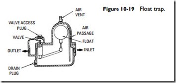
A float trap (see Figure 10-19) is operated by the rise and fall of a float connected to a discharge valve. The change of condensation level in the trap determines the level of the float. When the trap is empty, the float is at its lowest position and the discharge valve is closed. As the condensation level in the trap rises, the float also rises and gradually opens the valve. The pressure of the steam then pushes the condensation out of the valve. Because the opening of the valve is proportional to the flow of condensation through the trap, the discharge of condensation from the trap is generally continuous. On some float traps, a gauge glass is used to indicate the height of the condensation in the trap chamber.
One of the principal disadvantages of a float trap is the tendency of the valve to malfunction. Valve malfunctions can result from the
sticking of moving parts or excess steam leakage due to unequal expansion of the valve and seat.
Float traps are designed for steam pressures ranging from vac- uum conditions to 200 psig and are used to drain condensation from heating systems, steam headers, steam separators, laundry equipment, and other steam process equipment. When used in heating systems, a float trap should be equipped with a thermostatic air vent (see Float and Thermostatic T raps in this chapter).
