Velocity diagrams of the compressor stage
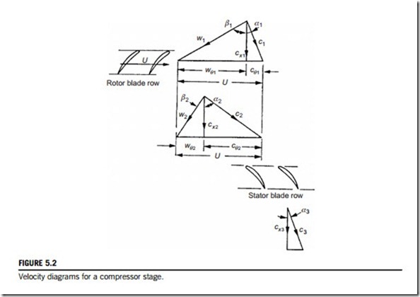
The velocity diagrams for the stage are given in Figure 5.2, and the convention is adopted through- out this chapter of accepting all angles and swirl velocities in this figure as positive. As for axial turbine stages, a normal compressor stage is one where the absolute velocities and flow directions
at stage outlet are the same as at stage inlet. The flow from a previous stage (or from the guide vanes) has a velocity c1 and direction α1; subtracting vectorially the blades speed U gives the inlet relative velocity w1 at angle β1 (the axial direction is the datum for all angles). Relative to the blades of the rotor, the flow is turned to the direction β2 at outlet with a relative velocity w2. By vectorially adding the blade speed U onto w2 gives the absolute velocity from the rotor, c2 at angle α2. The stator blades deflect the flow toward the axis, and the exit velocity is c3 at angle α3. For the normal repeating stage in a multistage compressor, c3 5 c1 and α3 5 α1. In Figure 5.2, it is noted that both the relative velocity in the rotor and the absolute velocity in the stator decrease. As shown later in this chapter, this diffusion of kinetic energy in the rotor and stator rows significantly influences the stage efficiency.
Related posts:
Incoming search terms:
- velocity diagram of axial flow compressor
- velocity diagram of axil flow compresser
- axial flow compressors and fans
- axial gas compressor
- velocity diagram for compressor stage
- velocity diagram for axial flow compressor axi
- velocity diagram for axial flow compressor
- schematic diagram of axil
- compressor stator velocity diagram
- axial flow compressor photo
- axial compressor stage velocity diagram
- a swirl diagram of axial compressor

