Steam Boiler Low-Water Cutoffs
Steam boilers must be provided with a water-level control device to shut off the automatic fuel-burning equipment when the water level in the boiler drops to a level too low for safe operation. This water- level control device is referred to as a low-water cutoff. The two types of low-water cutoff used on steam boilers are the float type and the probe type.
Note
According to Section 4 of the American Society of Mechanical Engineers (ASME) Boiler and Pressure Vessel Code, all residential steam boilers, regardless of their size or location, must have a low-water cutoff device installed.
A float low-water cutoff device consists of a cutoff switch operating in conjunction with a float located in the boiler water or in a float chamber installed next to the boiler. The float is connected through a linkage to a switch that operates a feed water valve. As the water level falls, the float drops with it until it reaches a point at which the feed water switch is actuated. If the water level continues to fall, a second switch connected to the float by a linkage is actuated, and the automatic fuel-burning equipment is shut off.
A probe low-water cutoff device depends on the flow of a low electrical current to control the operation of the automatic fuel- burning equipment. The electrical current flows from the probe through the water to keep the relay energized. When the water level falls, there will be a point at which the probe loses direct contact with the water. As a result, the contact is broken, and the flow of the electrical current is stopped. This, in turn, causes the relay to be energized, which results in shutting off the fuel-burning equipment. A probe low-water device cannot be used in the direct operation of feed water valves.
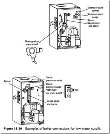
There are variety of ways to attach a low-water cutoff to a steam boiler (Figure 15-20). Some are designed to be attached to the glass gauge on the outside of the boiler. In this type of installation, the elevation of the low-water cutoff is already determined by the location of the glass gauge tappings on the side of the boiler.
Note
If there is a horizontal cast line on the outside of a gauge- mounted low-water cutoff, make certain it is located above the minimum safe water level specified by the boiler manufacturer.
Another type of low-water cutoff installation is to attach it directly to the side of the boiler. As shown in Figure 15-20, it is not connected to the water gauge. Its elevation is determined by the location of the pipe tappings on the boiler. The body of the control must be located at or above the manufacturer’s minimum safe water level.
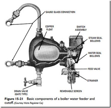
On some boilers, the low-water cutoff is combined with a water feeder to add water to the boiler when the water level falls below the safe operating limit. An example of one of these combined units is shown in Figure 15-21. They are available with either single or dual switch assemblies. The single double-throw switch assembly pro- vides a combination feeder and burner cutoff switch, with an extra terminal for line voltage with single-pole, double-throw service
(Figure 15-22). The dual switch assembly is used for line voltage burner service and for independent low- (or high-) voltage alarm, feed valve, or pump starter service. When an emergency condition occurs, the switch interrupts the current to the burner and shuts it off. When the emergency has passed, the water feeder takes over and feeds makeup water when needed for normal operation. On units equipped with dual switch assemblies, the alarm, feed valve, or pump starter switch actuates just before the burner switch cuts the
firing. A typical installation of a Watts 60 LWD boiler water feeder and cutoff on a steam boiler is illustrated in Figure 15-23.
A low-water cutoff without a boiler water feeder is usually adequate for providing automatic low-water safety protection for most small boilers (Figure 15-24). These units can be installed on any boiler having gauge glass connections.
Direct installation (built-in) low-water cutoffs are available for steam boilers with limited space in the boiler jacket (Figure 15-25). Each unit contains a switch assembly, a float and bellows, and a threaded barrel casting that fits into a 21⁄2-in tapping in the side of the boiler.

