OFF-DELAY CIRCUIT
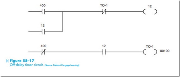
Some programmable logic controllers permit a timer to be programmed as on or off delay, but others permit only on-delay timers to be programmed. When a PLC permits only on-delay timers to be programmed, a simple circuit can be used to permit an on-delay timer to perform the function of an off-delay timer, Figure 58–17. To understand the action of the circuit, recall the operation of an off-delay timer. When the timer coil is energized the timed contacts change position immediately. When the coil is deenergized the contacts remain in their energized state for some period of time before returning to their normal state. In the circuit shown in Figure 58–17 it is assumed that contact 400 controls the action of the timer. Coil 400 is an internal relay coil located somewhere in the circuit. Coil 12 is an output and controls some external device. Coil TO-1 is an on-delay timer set for 100 tenths of a sec- ond. When coil 400 is energized, both 400 contacts change position. The normally open 400 contact closes and provides a current path to coil 12. The normally closed 400 contact opens and prevents a circuit from being completed to coil TO-1 when coil 12 energizes. Note that coil 12 turned on immediately when contact 400 closed. When coil 400 is deenergized, both 400 contacts return to their normal position. A current path is maintained to coil 12 by the now closed 12 contact in parallel
with the normally open 400 contact. When the normally closed 400 contact returns to its normal position a current path is established to coil TO-1 through the now closed 12 contact. This starts the time sequence of timer TO-1. After a delay of 10 seconds, the normally closed TO-1 contact opens and deenergizes coil 12, returning the two 12 contacts to their normal position. The circuit is now back in the state shown in Figure 58–16. Note the action of the circuit. When coil 400 was energized, output coil 12 turned on immediately. When coil 400 was deenergized, output 12 remained on for 10 seconds before turning off.
The number of internal relays and timers contained in a programmable logic controller is deter- mined by the memory capacity of the computer. As a general rule, PLCs that have a large I/O capacity will have a large amount of memory. The use of pro- grammable logic controllers has steadily increased since their invention in the late 1960s. A PLC can replace hundreds of relays and occupy only a fraction of the space. The circuit logic can be changed easily and quickly without requiring extensive hand rewiring. They have no moving parts or contacts to wear out, and their down time is less than that of an equivalent relay circuit. When replacement is
necessary, they can be reprogrammed from a media storage device.
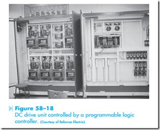
The programming methods presented in this text are general because it is impossible to include examples of each specific manufacturer. The concepts presented in this chapter, however, are common to all programmable controllers. A programmable logic controller used to control a DC drive is shown in Figure 58–18.

