BASIC COMPONENTS
Programmable logic controllers can be divided into four primary parts:
1. The power supply.
2. The central processing unit (CPU).
3. The programming terminal or program loader.
4. The I/O (pronounced eye-oh) rack.
The Power Supply
The function of the power supply is to lower the incoming AC voltage to the desired level, rectify it to direct current, and then filter and regulate it. The internal logic of a PLC generally operates on 5 to 24 volts DC depending on the type of controller. This voltage must be free of voltage spikes and other electrical noise and be regulated to within 5% of the required voltage value. Some manufacturers of PLCs build a separate power supply and others build the power supply into the central processing unit.
The CPU
The CPU, or central processing unit, is the “brains” of the programmable logic controller. It contains the microprocessor chip and related inte- grated circuits to perform all the logic functions. The microprocessor chip used in most PLCs is the same as that found in most home and business personal computers.
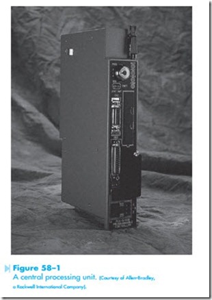
The central processing unit often has a key located on the front panel, Figure 58–1. This switch must be turned on before the CPU can be programmed. This is done to prevent the circuit from being changed or deleted accidentally. Other manufacturers use a software switch to protect the circuit. A software switch is not a physical switch. It is a command that must be entered before the program can be changed or deleted. Whether a physical switch or a software switch is used, they both perform the same function.
A central processing unit. (Courtesy of Allen-Bradley, a Rockwell International Company).
They prevent a program from being accidentally changed or deleted.
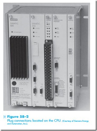
Plug connections on the central processing unit provide connection for the programming terminal and I/O racks, Figure 58–2. CPUs are designed so that once a program has been developed and tested it can be stored on some type of medium such as tape, disk, CD, or other storage device. In this way, if a central processor unit fails and has to be replaced, the program can be downloaded from the storage medium. This eliminates the time-consuming process of having to reprogram the unit by hand.
The Programming Terminal
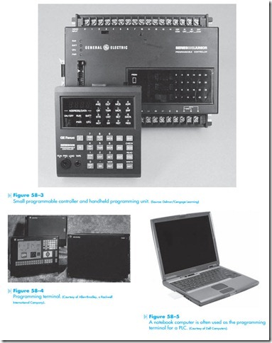
The programming terminal or loading terminal is used to program the CPU. The type of terminal used depends on the manufacturer and often the preference of the consumer. Some are small
handheld devices that use a liquid crystal display or light-emitting diodes to show the program, Figure 58–3. Some of these small units will display one line of the program at a time and others require the program to be entered in a language called Boolean.
Another type of programming terminal contains a display and keyboard, Figure 58–4. This type of terminal generally displays several lines of the program at a time and can be used to observe the operation of the circuit as it is operating.
Many industries prefer to use a notebook or lap- top computer for programming, Figure 58–5. An interface that permits the computer to be connected to the input of the PLC and software program is generally available from the manufacturer of the programmable logic controller.
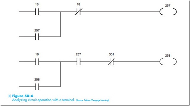
The terminal is used not only to program the PLC but also to troubleshoot the circuit. When the terminal is connected to the CPU, the circuit can be examined while it is in operation. Figure 58–6 illustrates a circuit typical of those which are seen on the display. Notice that this schematic diagram is different from the typical ladder diagram. All of the line components are shown as normally open or normally closed contacts. There are no NEMA symbols for pushbutton, float switch, limit switches, and so on. The programmable logic controller recognizes only open or closed contacts. It does not know if a contact is connected to a pushbutton, a limit switch, or a float switch. Each contact, however, does have a number. The number is used to distinguish one contact from another.
In this example, coil symbols look like a set of parentheses instead of a circle as shown on most ladder diagrams. Each line ends with a coil and each coil has a number. When a contact symbol has the same number as a coil, it means that the contact is controlled by that coil. The schematic in Figure 58–6 shows a coil numbered 257 and two contacts numbered 257. When coil 257 is energized, the programmable logic controller interprets both contacts 257 to be closed.
A characteristic of interpreting a diagram when viewing it on the screen of most loading terminals is that when a current path exists through a contact or if a coil is energized they will be highlighted on the display. In the example shown in Figure 58–6, coil 257, both 257 contacts, contact 16, and contact
18 are drawn with dark heavy lines, illustrating that they are highlighted or illuminated on the display. Highlighting a contact does not means that it has changed from its original state. It means that there is a complete circuit through that contact. Contact 16 is highlighted, indicating that coil 16 has energized and contact 16 is closed and providing a complete circuit. Contact 18, however, is shown as normally closed. Because it is highlighted, coil 18 has not been energized because a current path still exists through contact 18. Coil 257 is shown high- lighted, indicating that it is energized. Because coil 257 is energized, both 257 contacts are now closed, providing a current path through them.
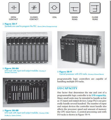
When the loading terminal is used to load a pro- gram into the PLC, contact and coil symbols on the keyboard are used, Figure 58–7. Other keys permit specific types of relays, such as timers, counters, or retentive relays to be programmed into the logic of the circuit. Some keys permit parallel paths, generally referred to as down rungs, to be started and ended. The method employed to program a PLC is specific to the make and model of the controller. It is generally necessary to consult the manufacturer’s literature if you are not familiar with the specific programmable logic controller.
The I/O Rack
The I/O rack is used to connect the CPU to the outside world. It contains input modules that carry information from control sensor devices to the CPU and output modules that carry instructions from the CPU to output devices in the field. I/O racks are shown in Figures 58–8A and 58–8B. Input and output modules contain more than one input or output. Any number from 4 to 32 is common, depending on the manufacturer and model of PLC. The modules shown in Figure 58–8A can each handle 16 connections. This means that each input module can handle 16 different input devices such as pushbutton, limit switches, proximity switches, float switches, and so on. The output modules can each handle 16 external devices such as pilot lights, solenoid coils, or relay coils. The operating voltage can be either alternating or direct cur- rent, depending on the manufacturer and model of controller, and is generally either 120 or 24 volts.
