Braze Welding Pipe
Braze welding is another bonding process that does not melt the base metal. In this respect, it resembles both soldering and brazing.
Brazing and braze welding operate under essentially the same basic principles. For example, both use nonferrous filler metals that melt above 880°F but below the melting point of the base metal. They differ primarily in application and procedure.
The braze-welding process follows most of the steps previously described for brazing but will differ principally as follows:
1. Edge preparation is necessary in braze welding and is essen- tially similar to that employed in gas welding. The edges must be prepared before the surfaces are cleaned.
2. A suitable filler metal is used instead of a brazing alloy.
The filler metal will flow throughout the joint by capillary attrac- tion. Flanges that are to be brazed to copper pipes must be of copper or what is known as brazing metal (98 percent copper and 2 percent tin), as gunmetal flange would melt before the brazing alloy ran.
Welding Pipe
Oxyacetylene welding (gas welding) is probably the most common welding process used for joining pipe and fittings, particularly on smaller installations. Arc welding is also very popular.
Pipe welding should be done only by a skilled and experienced worker. The equipment and the procedure used are much more com- plicated than those used with soldering, brazing, or braze welding.
Welding forms a joint by melting (fusing) the metal at tempera- tures above its melting point. The filler metal, electrodes, or welding rods used must be suitable for use with the base metal to be welded, and the procedure used should be such as to ensure complete pene- tration and thorough fusion of the deposited metal with the base metal. The welding process is employed in many piping installa- tions, but especially those in which large-diameter pipes are used.
Manufactured steel welding fittings are available for almost every conceivable type of pipe connection. These steel welding fit- tings can be divided into the following two principal categories:
• Butt-welding fittings
• Socket-welding fittings
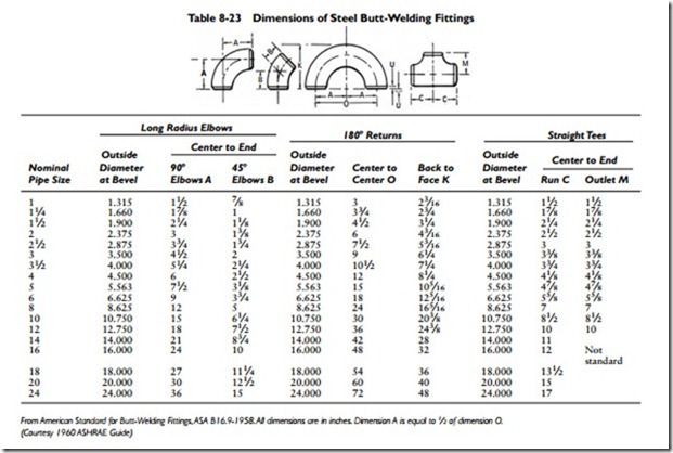
Butt-welding fittings (see Table 8-23) have ends that are cut square or beveled 371⁄2° for wall thicknesses under 3⁄16 inch. Wall thicknesses ranging from 3⁄16 inch to 3⁄4 inch are beveled 371⁄2°. For walls ranging from 3⁄4 inch to 13⁄4 inches thick, the bevel is U- shaped.
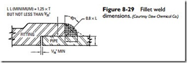
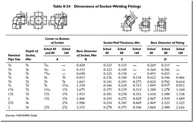
Socket-welding fittings (see Table 8-24) have a machined recess or socket for inserting the pipe. A fillet weld is made between the pipe wall and the socket end of the fitting. The fillet weld is approximately triangular in cross-section, the throat lying in a plane of approximately 45° with respect to the surfaces of the part joined. As shown in Figure 8-29, the minimum thickness of the socket wall (L) is 1.25 times the nominal pipe thickness (T) for the designated schedule number of the pipe. Socket-welding fittings are generally limited in use to nominal pipe sizes 3 inches and smaller.
In addition to butt- and socket-welding fittings, flange fittings are also available for welding in sizes ranging from 1⁄2 inch to 24 inches.
Gas Piping
The gas pipe installations in which gas-fired furnaces, boilers, heaters, or other gas appliances are used deserve special attention because of the volatile and highly flammable nature of the fuel. Special attention should be given to the installation of gas piping to ensure against leakage.
The installation and replacement of gas piping should be done only by qualified workers who have the necessary skills and experience.
The following recommendations are offered as a guide for installing and replacing gas piping:
• All work should be done in accordance with the building, heating, and plumbing codes and standards of the authorities having local jurisdiction. These take precedence over national codes and standards.
• In an existing installation, the gas supply to the premises and all burners in the system must be shut off before work begins.
• When installing a system, size the pipes according to the amount of gas to be delivered to each outlet and at the proper pressure. The length of pipe runs and number of outlets are the main determining factors.
• Use a piping material recommended by the local authorities having jurisdiction. Never bend gas piping because it may cause the pipe walls to crack and leak gas. Use fittings for making turns in gas piping. Take all branch connections from the top or side of horizontal pipes (never from the bottom).
• Locate the gas meter as close as possible to the point at which the gas service enters the structure.
• Make certain all pipes are adequately supported so that no unnecessary stress is placed on them.
• Offsets should be 45° elbows rather than 90° fittings in order to reduce the friction to the flow of gas.
• Check for gas leaks by applying a soap-and-water solution to the suspected area. Never use matches, candles, or any other flame to locate the leak.
Insulating Pipes
Insulating the supply pipes in a low-pressure steam or hot-water space heating system will reduce unwanted heat loss and improve the heating efficiency of the system. The return pipes in a hot-water heating system should also be insulated so that the water reaches
the boiler with a minimum of heat loss. Do not insulate the return pipes in a steam heating system. Uninsulated pipes will aid in the condensation of any steam that has succeeded in bypassing the thermostatic traps and entering the returns.
The pipe insulation material must be noncombustible, durable, and resistant to moisture. Furthermore, it should be able to retain its original physical shape and insulating properties after becoming wet and drying out.
Fiberglass is used to insulate steam or hot-water heating pipes. It can be easily applied to the pipe, requiring little more than ordinary cutting shears or a sharp knife.
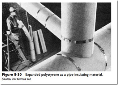
Another effective pipe-insulating material is expanded polystyrene (see Figure 8-30).
Your local building supply dealer should be able to answer any questions you may have about pipe-insulting materials. The manufacturers of these materials also generally provide detailed instruc- tion about how to apply them. You should not have any difficulty if you carefully read and follow these instructions.
Piping Details
Each piping installation will have design or layout problems that the fitter must solve. Many of these problems, such as installing dirt pockets or siphons, are quite simple for the pipe fitter to handle.
More-complicated layout problems are solved by calculating and installing lift fittings, swivels and offsets, and drips. These and other piping details are described in the sections that follow.
Related posts:
Incoming search terms:
- Pipe Fittings mail
- Pipe Fittings and Flanges mail
- Pipes and Fittings mail
- Pipe Making Machinery mail
- Fibreglass piping (flanges pipes) mail
- japan Pipes And Fittings mail
- Plumbing - Pipes Fittings Flanges Elbows
- piping fitting
- Welded Pipe mail
- Pipes Pipe Fittings and Pipe Flanges mail
- 371 steel Pipes lv mail
- pipe fitting&pipeing details
- pipe and fittings dealers mail
- PIPE 600 CONGESTION
- HVAC pipes welding procedure
- arc welding in ms pipe in hvac
- 86 Fiberglass Pipes mail
- welding and soldering equipments dealers mail


