Impedance Relays
An impedance relay (see Figure 6-37) is used to provide lockout and remote reset in refrigeration, air-conditioning, and other
systems. A typical wiring diagram for a low-voltage impedance relay is shown in Figure 6-38. A low-voltage relay requires the use of a transformer with an open circuit secondary of between 24 and 27 volts AC.
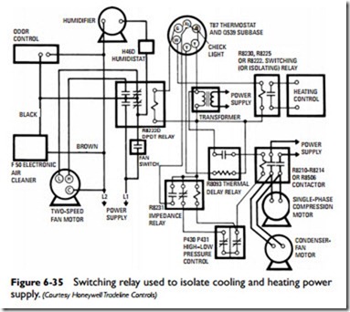
As shown in Figure 6-38, one pair of contacts is normally open and the other pair is normally closed. During normal operation, the normally closed contacts of the pressure controls (i.e., the low- pressure and high-pressure cutout switches) and the motor overloads short out the impedance relay coil so that the compressor contactor pulls in. If one of the pressure controls or overloads opens, the impedance relay coil is energized in series with the contactor coil and most of the available voltage is used by the high impedance of the relay coil. Because insufficient voltage remains to operate the contactor coil, the contactor drops out and compressor operation stops.
As the impedance relay pulls in, its normally closed contacts open to keep the contactor out, even though the pressure control or
overload (automatic reset) remakes. The system can be reset by breaking the contactor circuit to allow the impedance relay to drop out. In most systems, this is accomplished by moving the thermo- stat subbase switch to off and back to cool again.

