Blower and Motor
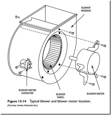
The blower assembly consists of the blower wheel housing, the blower wheel, the blower motor, and the blower motor capacitor. The function of the blower is to draw air into the furnace through the return air duct, force the air around the internal surfaces of the heat exchanger to pick up heat, and then deliver the warm air to the interior of the house through the supply ducts. The combustion air required for the combustion process is drawn in through an air inlet
scoop on the side of the blower wheel housing. The amount of combustion air is regulated by an air adjustment dial located on the out- side of the housing. It can be manually changed by moving the dial setting.
As shown in Figure 12-14, the blower motor is attached to the side of the blower wheel housing. The motor shaft rotates the blower wheel inside the blower wheel housing. The blower motor capacitor, which assists in starting the blower motor, is attached to the outside edge of the blower wheel housing.
Both direct-drive and belt-drive blowers are used with oil-fired furnaces. These blowers and motors are identical to those used in gas-fired furnaces. Read the section Blowers and Motors in Chapter 11, “Gas Furnaces” for additional information. The function of the blower is to blow heat through the duct system into the rooms of the structure.
Oil furnaces equipped with direct-drive blowers operated by commutating motors are capable of adjusting the furnace heat out- put and blower speed to the heat requirements of the structure. In other words, their operation increases with the demand for heat and decreases when there is none, thereby improving indoor com- fort while reducing energy costs. These furnaces are sometimes called dual-capacity, variable-speed oil furnaces.
Combustion Air Blowers
High-efficiency oil furnaces are often equipped with small blowers designed to provide a steady supply of combustion air to the burner. These small combustion air blowers operate on not more than 1⁄6 horsepower or less.
Pressure switches are used with combustion air blowers to sense blower speed and whether the flue is blocked. Older conventional oil furnaces used centrifugal switches instead of pressure switches.
Cleanout and Observation Ports
As shown in Figure 12-2, an oil furnace typically is provided with one or two cleanout ports to allow access to the heat exchanger for cleaning (soot removal). The observation port allows monitoring of the inside of the heat exchanger during the operation of the furnace.
Vent Opening
The vent opening connects the furnace to a flue pipe for venting the combustion gases to the outdoors. Many of the modern oil furnaces connect the flue pipe to a sidewall of the house. Traditional oil furnaces vented these gases through a flue pipe connected to the chimney.
Air Filter
A forced-warm-air oil furnace is supplied with either a disposable air filter or a permanent (washable) one. A filter is not used with a gravity warm-air oil furnace, because it will obstruct the air- flow.
A disposable air filter should be inspected on a regular basis and replaced when dirty. Always replace the air filter with one of the same size and type of filter media. This information is usually found on a label attached to the filter.
A permanent air filter must also be regularly inspected. When it is dirty, it must be removed and cleaned. The usual method is to vacuum it and then to wash it in a soap or detergent and water solution. Additional information about air filters is found in Chapter 11, “Gas Furnaces,” and Chapter 12, “Air Cleaners and Filters” in Volume 3.
Installing an Oil Furnace
An oil furnace must be properly set up and installed by a certified oil heat technician, a representative of the oil furnace manufacturer, or an HVAC professional with equivalent experience.
The size (Btu output capacity) of the oil furnace selected for the heating system is determined by the calculated heat loss for the structure. See Chapter 4, “Sizing Residential Heating and Air Conditioning Systems.”
Related posts:
Incoming search terms:
- Air Blowers Air Cleaners mail
- structure of oil fired furnace
- Structure Combustion Blower
- observation port oil
- internel structure of blower
- internal structure of blower
- internal structure of air blower
- Combustion oil furnace filter
- blower to burner in a oil fired furnace
- blower motor capacitor
- typical furnace blower size
