STARTING
Most large wound rotor motors use a method of step starting as opposed to actual variable resistors. Step starting is similar to shifting the gears in the transmission of an automobile. The trans- mission is placed in first gear when the car is first started. As the car gains speed, the transmission is shifted to second gear, then third gear, and so on until the car is operating in its highest gear. When a wound rotor motor is step started, it begins with maximum resistance connected in the rotor circuit. As the motor speed increases, resistance is shorted out of the circuit until the windings of the rotor are shorted together. The number of steps can vary from one motor to another, depending on the size of the motor and how smooth a starting action is desired.
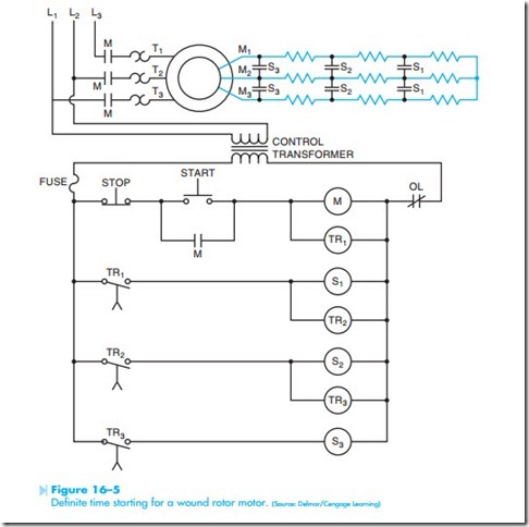
There are different control methods used to short out the steps of resistance when starting a wound rotor motor. Some controllers sense the amount of current flow to the stator. This method is known as current limit control. Another method detects the speed of the rotor. This method is known as slip frequency control. One of the most common methods uses time relays to control when resistance is shorted out of the circuit. This method is known as definite time control. Figure 16–5 shows a schematic diagram of a time-controlled starter for a wound rotor motor. In this schematic, the motor circuit is shown at the top of the diagram. A control transformer is used to step the line voltage down to the value of voltage used in the control circuit. The operation of the circuit is as follows:
1. When the start button is pressed, a circuit is completed through M motor starter coil, TR1 coil, and the overload contact. When M coil energizes, all M contacts close. The three large load contacts located at the top of the diagram close and connect the stator winding to the line. The M contact located beneath the start button is known as the holding, sealing, or maintaining contact. Its job is to provide a continued circuit to the M coil when the start button is released. The motor now begins to run in its lowest speed. Maximum resistance is connected in the rotor circuit.
2. TR1 relay is a timer. For this example, it shall be assumed that all timers are set for a delay of 3 seconds. When TR1 coil energizes, it begins a time operation. After 3 seconds, TR1 contact closes. This completes a circuit to S1 coil and TR2 coil.
3. When S1 coil energizes, both S1 contacts close and short out the last three resistors in the rotor circuit. This causes the motor to accelerate to the next higher speed. When TR2 coil energizes, it begins timing.
4. At the end of a 3-second time period, TR2 contact closes and completes a circuit to coil S2 and TR3.
5. When S2 coil energizes, both S2 contacts close and short out the next set of resistors. This permits the motor to accelerate to a higher speed. When TR3 coil energizes, it begins its timing sequence.
6. After a 3-second time period, contact TR3 closes and provides a complete circuit for coil S3. This causes both S3 contacts to close and short out the last set of resistors. The motor now accelerates to its highest speed.
7. When the stop button is pressed, the circuit to coil M and coil TR1 is broken. When coil M deenergizes, all M contacts open. This disconnects the stator winding from the line. When TR1 coil deenergizes, contact TR1 opens immediately. This deenergizes coil S1 and coil TR2. When coil S1 deenergizes, both S1 contacts return to their open position.
When coil TR1 deenergizes, contact TR2 opens immediately. When contact TR2 opens, it breaks the circuit to coil S2 and coil TR3. When coil S2 deenergizes, both S2 contacts reopen. Contact TR3 opens immediately when coil TR3 deenergizes. This causes coil S3 to deenergize and open both S3 contacts.
8. If the fuse should blow, or the overload con- tact open, it has the same effect as pressing the stop button.
