Brushless DC Motors
Brushless direct current motors have become very popular for operating variable speed air handlers found in many residential central heating and cooling systems. The typical air handler is powered by a multispeed motor that can generally operate at three speeds. When the fan motor is started, how- ever, it operates at its set speed until it is turned off. Basically, the blower motor is either full on or completely off. Variable speed air handlers permit the motor to operate at different speeds in accord with the demands of the system. Many variable speed air handlers are operated at a low speed continuously to maintain air circulation throughout the dwelling at all times. When the heating or cooling system turns on, the fan speed can be increased gradually and in steps instead of all at once.
Variable speed air handlers exhibit several advantages over air handlers that operate at a single speed. Some of these advantages are:
Dust collection. Single speed air handlers pull dust through the filter at a high rate of speed. This lessens the filter’s ability to trap dust particles. Variable speed air handlers operate at a very low speed most of the time, causing more dust particles to be collected by the filter.
Less temperature variation. Typically, the inside temperature will vary from three to five degrees before the heating or cooling system turns on. The variable speed air handler can be operated at different speeds between the cycling of the heating or cooling system to provide more or less air flow as needed. This can greatly reduce the temperature variation and permits the temperature to remain closer to the comfort zone setting.
Better humidity control during cooling. When the air-conditioning compressor starts, the speed of the air handler is increased gradually instead of all at once. This permits the warm air to flow across the evaporator coil at a slower rate, permitting the coil to rapidly cool down. This rapid cooldown results in increased moisture removal.
THE BRUSHLESS DC MOTOR
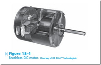
The brushless DC motor operates by converting direct current into three-phase alternating cur- rent at different frequencies. The motor contains a permanent magnet rotor, a stator, and the electronics necessary to change direct current into three-phase alternating current, Figure 18–1. The speed of the motor is determined by the frequency of the three-phase current. The motor operates on the principle of a rotating magnetic field very similar to that of a three-phase induction motor. The brush- less DC motor, however, is not an induction motor. It does not depend on current being induced into the rotor to produce a rotor magnetic field. Because permanent magnets supply the rotor magnetic field, the brushless DC motor does not exhibit the high inrush current during starting that is a characteristic of
induction type motors. The starting current and the running current of the motor are basically the same. This feature greatly reduces the current-handling requirement of the electronic components needed to change direct current into three-phase alternating current.
The factors that determine the amount of torque produced by the brushless DC motor are the same as those for any other electric motor:
1. Strength of the magnetic field of the stator.
2. Strength of the magnetic field of the rotor.
3. Phase angle difference between rotor and stator flux.
Because the rotor magnetic field is supplied by permanent magnets, the flux of the rotor and stator are always in phase with each other. This produces a strong torque for this type of motor.
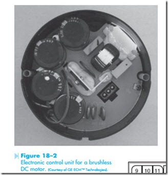
The electronic components necessary to change single-phase alternating current into direct cur- rent and then into three-phase alternating current are located inside the motor housing, Figure 18–2. Most variable frequency type controls first change alternating current into direct current because it is a simpler process to produce multiphase alternating current from direct current than to change the frequency and number of phases of an existing alternating current source.
Brushless DC motors are operated in one of two modes, the thermostat mode or the variable speed mode. When used in the thermostat mode, the motor is controlled by a 24-VAC signal from the thermostat. When used in the variable speed mode, the motor is controlled by a pulse width modulating signal.
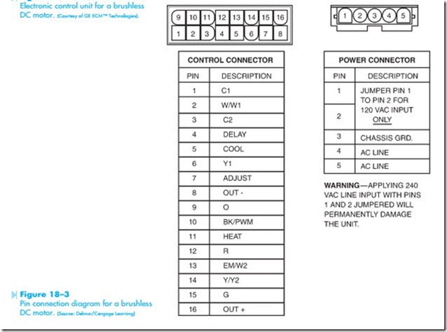
The motor is provided with two terminal connections. One is a 16-pin connector and is called the control connector. This connector receives the information necessary to control the operation of the motor. The other connection is a 5-pin connector and is called the power connector. This connector provides the power to operate the motor. A pin connection diagram is shown in Figure 18–3.
Brushless DC motors can generally be obtained in 1/3, 1/2, 3/4, or 1 horsepower ratings. They can exhibit efficiency as high as 82% and can operate on 120/240 and 277 VAC at 50 or 60 Hz. The speed range is from 300 to 1,200 RPM. Although the motor can be operated at 1,200 RPM, it is generally recommended not to operate the motor above 1,050 RPM when used for continuous operation.
Electronic Control
The brushless DC motor is controlled by a circuit board located in the air handler. The board supplies both direct current to the motor and the signals that determine motor speed. Some boards are preset at the factory for the specific type of air handler unit. Other boards contain DIP (Dual Inline Package) switches that permit the air handler to be set for different operating conditions. Typical DIP switch configurations for some systems are:
Switches 1 and 2. Set for system tonnage. Switches 3 and 4. Set for 300, 400, or 450 cfm/ton. Switches 5 and 6. Set for time delay or mode. Switches 7 and 8. Set for desired heating flow.


