Hot Water
Within buildings, hot water is the fluid that is most commonly used for heat- distribution. The amount of heat that is transferred is proportional to the temperature difference between supply and return. Maximizing the supply-return temperature difference minimizes the water quantity and pipe size requirements. Unfortunately, the economy of smaller water quantities with a high temperature difference creates a need for larger, and more costly, heaters and heat exchangers. The design challenge is thus to find the best balance between cost to install and cost to operate.
For general use, in buildings where the public may touch the pipes, the normal operating supply temperature is 180°F. In the past, return temperatures were 160°F, but temperatures of 150°F, or even 140°F, are now often used for overall operating economy. Systems can also be designed to operate with a 180°F flow, except under peak load conditions. Peak load conditions hardly ever occur, but if they do, then the flow temperature can be raised as high as 200°F.
These systems can operate at very low pressure, since the only requirement is that the pipes remain full. For working temperatures above 200°F, at sea level, systems must be pressurized to avoid the possibility of the water boiling.
As discussed in the previous chapter, radiant floors operate with a maximum surface temperature of 84°F. They need heating water at 120°F or less, much cooler than 180°F. This can be achieved by mixing cool return water with the 180°F water to provide a supply to the floor at 120°F or less. Alternatively, and very fuel efficiently, they can be supplied from a condensing boiler or ground source heat pump, both of which have a maximum flow temperature of about 120°F.
For distribution between buildings, higher temperatures—up to 450°F—can be used. The high temperature hot water is passed through a heat exchanger in each building to provide the, typically, 180°F water for distribution around the building and for heating domestic hot water.
Pipes should be insulated to avoid wasteful heat loss. Thus pipes in the boiler room should be insulated, but pipes in a zone that is feeding a radiator may not need to be insulated, since the heat loss just adds to the radiator out- put. However, if a pipe presents an exposed surface that could cause a burn, insulation should be used.
Insulation thickness should take into account the temperature difference between the water and surroundings. Thus, rather thicker insulation should be used on pipes that run outside a building than inside the building.
9.4.1 Energy Efficiency in Hot Water Systems
There are many ways to control and increase energy efficiency in the hot water systems. The control method that we will discuss is the outdoor reset, a common control strategy that takes advantage of the temperature differential between the cold outside and the warm inside the building to adjust the heat output. Then we will consider pumps and the energy savings that we can obtain through reducing the flow in hot water systems:
The heat loss from a building in cold weather is proportional to the difference between the temperature inside the building and the temperature outside the building. Similarly, the heat output from a convection heater is roughly proportional to the difference in between the space temperature and the heating-supply-water temperature. Outdoor reset makes combined use of these two relationships by adjusting the heating-water temperature with changes in outdoor temperature. With the correct schedule, the water flow remains constant and the heat output just balances the building heat loss.
This outdoor reset system has advantages, but it does mean that the heating water flow is 100% all through the heating season. This continuous full flow involves a significant pumping cost.
In the last section we noted that the head is proportional to the flow1.85. The pumping power is proportional to the head, times the flow. So, doubling the flow requires
2 ( 21.85) = 7.2 times the power!
Here is an incentive to reduce flow. If, instead of modulating the water temperature, it remained constant at, say 180°F, and the flow was varied by thermostatic valves, the required flow would be much less than 100% most of the time. In fact, since most heating systems are oversized, the flow would never reach 100%. However, as soon as the flow varies, we need a method of varying the pump capacity.
In the following sections, we will consider two methods of varying pump capacity:
1. Varying pump speed
2. Using pumps in parallel
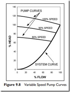
Varying Pump Speed Variable speed drives are now readily available and can be used to adjust pump speed according to load. The pump curve remains the same shape, but shrinks as the speed reduces. Typical pump curves for various speeds are shown in Figure 9.8.
The arrows in the figure indicate that the head is about 25% at 50% speed and 50% flow, while the power consumption is about 10% at 50% flow.
The figure also shows the pump shaft power, which is the power used by the pump, without consideration of any bearing or motor inefficiencies. Since motor efficiency generally drops significantly at low speeds, the overall reduction in power is much less than the figure indicates at low flows.
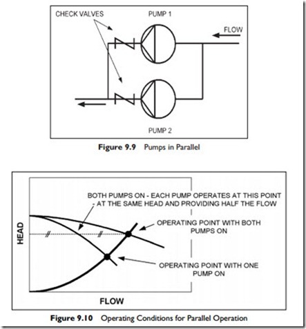
Pumps In Parallel Another way to reduce flow is to use two identical pumps in parallel. Each pump experiences the same head, and their flows add to equal the system flow. A check valve is included with each pump, so that when only one pump is running, the water cannot flow backwards through the pump that is “off.” The piping arrangement is shown in Figure 9.9.
With both pumps running, the design flow is at the system operating point. When one pump is shut off, the flow and head drop to the single pump curve as shown in Figure 9.8. This flow is between 70% and 80% of full flow, depending on pump design. Note that the power required by the single pump is slightly higher when running on its own and the motor must be sized for this duty.
The use of parallel pumps for a heating system has two advantages: First, it produces a substantial reduction in energy use for all the hours the system is using only one pump; second, it provides automatic stand-by to at least 70% duty when one of the pumps fails.

