Introduction
In Chapter 1 we introduced the seven main air-conditioning processes and the task of establishing objectives for air-conditioning design. In this chapter we will consider How these processes are described graphically in the psychrometric chart. How these processes are combined to form an air-conditioning system.
The range of heating, ventilating and air-conditioning systems. How system choices are made.
Introducing the Psychrometric Chart
Many of the air-conditioning processes involve air that is experiencing energy changes. These changes arise from changes in the air’s temperature and its moisture content. The relationships between temperature, moisture content, and energy are most easily understood using a visual aid called the “psychrometric chart.”
The psychrometric chart is an industry-standard tool that is used to visualize the interrelationships between dry air, moisture and energy. If you are responsible for the design or maintenance of any aspect of air conditioning in buildings, a clear and comfortable understanding of the chart will make your job easier.
Initially, the chart can be intimidating, but as you work with it you will discover that the relationships that it illustrates are relatively easy to understand. Once you are comfortable with it, you will discover that it is a tool that can make it easier to troubleshoot air-conditioning problems in buildings. The ASHRAE course, Fundamentals of Thermodynamics and Psychrometrics1 goes into great detail about the use of the chart. That course also provides calculations and discussion about how the chart can be used as a design and troubleshooting tool.
In this course, however, we will only introduce the psychrometric chart, and provide a very brief overview of its structure.
The Design of the Psychrometric Chart
The psychrometric chart is built upon two simple concepts.
1. Indoor air is a mixture of dry air and water vapor.
2. There is a specific amount of energy in the mixture at a specific temperature and pressure.
Psychrometric Chart Concept 1: Indoor Air is a Mixture of Dry Air and Water Vapor. The air we live in is a mixture of both dry air and water vapor. Both are invisible gases. The water vapor in air is also called moisture or humidity. The quantity of water vapor in air is expressed as “pounds of water vapor per pound of air.”
This ratio is called the “humidity ratio,” abbreviation W and the units are pounds of water/pound of dry air, lbw/lbda, often abbreviated to lb/lb.
The exact properties of moist air vary with pressure. Because pressure reduces as altitude increases, the properties of moist air change with altitude.
Typically, psychrometric charts are printed based on standard pressure at sea level. For the rest of this course we will consider pressure as constant.
To understand the relationship between water vapor, air and temperature, we will consider two conditions:
First Condition: The temperature is constant, but the quantity of water vapor is increasing.
If the temperature remains constant, then, as the quantity of water vapor in the air increases, the humidity increases. However, at every temperature point, there is a maximum amount of water vapor that can co-exist with the air. The point at which this maximum is reached is called the saturation point. If more water vapor is added after the saturation point is reached, then an equal amount of water vapor condenses, and takes the form of either water droplets or ice crystals.
Outdoors, we see water droplets in the air as fog, clouds or rain and we see ice crystals in the air as snow or hail. The psychrometric chart only considers the conditions up to the saturation point; therefore, it only considers the effects of water in the vapor phase, and does not deal with water droplets or ice crystals.
Second Condition: The temperature is dropping, but the quantity of water vapor is constant.
If the air is cooled sufficiently, it reaches the saturation line. If it is cooled even more, moisture will condense out and dew forms.
For example, if a cold canned drink is taken out of the refrigerator and left for a few minutes, the container gets damp. This is because the moist air is in contact with the chilled container. The container cools the air that it contacts to a temperature that is below saturation, and dew forms. This temperature, at which the air starts to produce condensation, is called the dew point temperature.
Relative Humidity
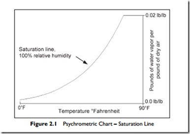
Figure 2.1 is a plot of the maximum quantity of water vapor per pound of air against air temperature. The X-axis is temperature. The Y-axis is the proportion of water vapor to dry air, measured in pounds of water vapor per pound of dry air. The curved “maximum water vapor line” is called the “saturation line.” It is also known as 100% relative humidity, abbreviated to 100% rh. At any point on the saturation line, the air has 100% of the water vapor per pound of air that can coexist with dry air at that temperature.
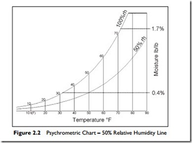
When the same volume of air contains only half the weight of water vapor that it has the capacity to hold at that temperature, we call it 50% relative humidity or 50% rh. This is shown in Figure 2.2. Air at any point on the 50% rh line has half the water vapor that the same volume of air could have at that temperature.
As you can see on the chart, the maximum amount of water vapor that moist air can contain increases rapidly with increasing temperature. For example, moist air at the freezing point, 32°F, can contain only 0.4% of its weight as
water vapor. However, indoors, at a temperature of 72°F the moist air can contain nearly 1.7% of its weight as water vapor—over four times as much.
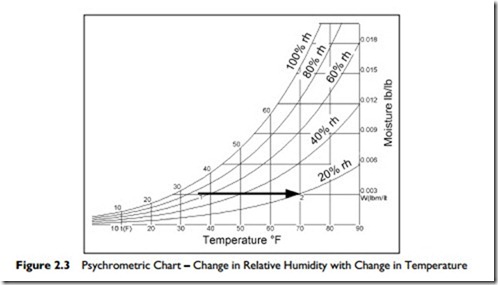
Consider Figure 2.3, and this example:
On a miserable wet day it might be 36°F outside, with the air rather humid, at 70% relative humidity. Bring that air into your building. Heat it to 70°F.
This brings the relative humidity down to about 20%. This change in relative humidity is shown in Figure 2.3, from Point 1 : 2. A cool damp day outside provides air for a dry day indoors! Note that the absolute amount of water vapor in the air has remained the same, at 0.003 pounds of water vapor per pound of dry air; but as the temperature rises, the relative humidity falls.
Here is an example for you to try, using Figure 2.3.
Suppose it is a warm day with an outside temperature of 90°F and relative humidity at 40%. We have an air-conditioned space that is at 73°F. Some
of the outside air leaks into our air-conditioned space. This leakage is called infiltration.
Plot the process on Figure 2.3.
Find the start condition, 90°F and 40% rh, moisture content 0.012 lb/lb.
Then cool this air: move left, at constant moisture content to 73°F.
Notice that the cooled air now has a relative humidity of about 70%.
Relative humidity of 70% is high enough to cause mold problems in buildings. Therefore in hot moist climates, to prevent infiltration and mold generation, it is valuable to maintain a small positive pressure in buildings.
Psychrometric Chart Concept 2: There is a specific amount of energy in the air mixture at a specific temperature and pressure.
This brings us to the second concept that the psychrometric chart illustrates. There is a specific amount of energy in the air water-vapor mixture at a specific temperature. The energy of this mixture is dependent on two measures:
1. The temperature of the air.
2. The proportion of water vapor in the air.
There is more energy in air at higher temperatures. The addition of heat to raise the temperature is called adding “sensible heat.” There is also more energy when there is more water vapor in the air. The energy that the water vapor contains is referred to as its “latent heat.”
The measure of the total energy of both the sensible heat in the air and the latent heat in the water vapor is commonly called “enthalpy.” Enthalpy can be raised by adding energy to the mixture of dry air and water vapor. This can be accomplished by adding either or both
e Sensible heat to the air
e More water vapor, which increases the latent heat of the mixture
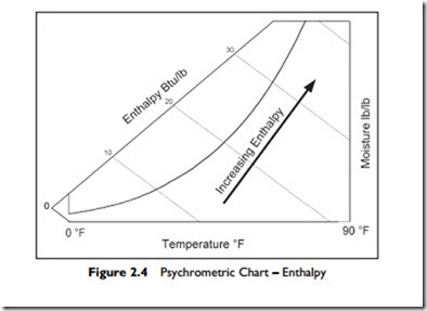
On the psychrometric chart, lines of constant enthalpy slope down from left to right as shown in Figure 2.4 and are labeled “Enthalpy.”
The zero is arbitrarily chosen as zero at 0°F and zero moisture content. The unit measure for enthalpy is British Thermal Units per pound of dry air, abbreviated as Btu/lb.
Heating
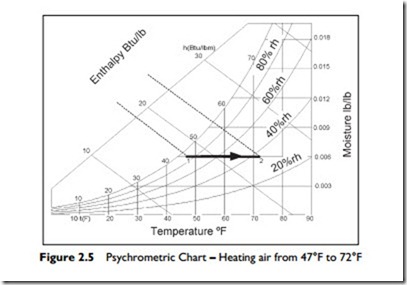
The process of heating involves the addition of sensible heat energy. Figure 2.5 illustrates outside air at 47°F and almost 90% relative humidity that has been heated to 72°F. This process increases the enthalpy in the air from approximately 18 Btu/lb to 24 Btu/lb. Note that the process line is horizontal because no water vapor is being added to, or removed from the air—we are just heating the mixture. In the process, the relative humidity drops from almost 90% rh down to about 36% rh.
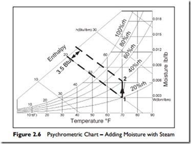
Here is an example for you to try. Plot this process on Figure 2.6.
Suppose it is a cool day with an outside temperature of 40°F and 60% rh. We have an air-conditioned space and the air is heated to 70°F. There is no change in the amount of water vapor in the air. The enthalpy rises from about 13 Btu/lb to 20 Btu/lb, an increase of 7 Btu/lb.
As you can see, the humidity would have dropped to 20% rh. This is quite dry so let us assume that we are to raise the humidity to a more comfortable 40%. As you can see on the chart, this raises the enthalpy by an additional 3.5 Btu/lb.
Humidification
The addition of water vapor to air is a process called “humidification.” Humidification occurs when water absorbs energy, evaporates into water vapor, and mixes with air. The energy that the water absorbs is called “latent heat.”
There are two ways for humidification to occur. In both methods, energy is added to the water to create water vapor.
1. Water can be heated. When heat energy is added to the water, the water is transformed to its gaseous state, steam, that mixes into the air. In Figure 2.6, the vertical line, from Point 1 to Point 2, shows this process. The heat energy, 3.5 Btu/lb, is put into the water to generate steam (vaporize it), which is then mixed with the air.
In practical steam humidifiers, the added steam is hotter than the air and the piping loses some heat into the air. Therefore, the air is both humidified and heated due to the addition of the water vapor. This combined humidification and heating is shown by the dotted line which slopes a little to the right in Figure 2.6.
2. Water can evaporate by spraying a fine mist of water droplets into the air.
The fine water droplets absorb heat from the air as they evaporate. Alter- natively, but using the same evaporation process, air can be passed over a wet fabric, or wet surface, enabling the water to evaporate into the air.
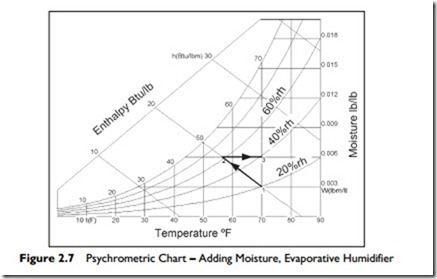
In an evaporative humidifier, the evaporating water absorbs heat from the air to provide its latent heat for evaporation. As a result, the air temperature drops as it is humidified. The process occurs with no external addition or removal of heat. It is called an adiabatic process. Since there is no change in the heat energy (enthalpy) in the air stream, the addition of moisture, by evaporation, occurs along a line of constant enthalpy.
Figure 2.7 shows the process. From Point 1, the moisture evaporates into the air and the temperature falls to 56°F, Point 2. During this evaporation, the relative humidity rises to about 65%. To reach our target of 70°F and 40% rh we must now heat the moistened air at Point 2 from 56°F to 70°F, Point 3, requiring
3.5 Btu/lb of dry air.
To summarize, we can humidify by adding heat to water to produce steam and mixing the steam with the air, or we can evaporate the moisture and heat the moistened air. We achieve the same result with the same input of heat by two different methods.
The process of evaporative cooling can be used very effectively in a hot, dry desert climate to pre-cool the incoming ventilation air. For example,
outside air at 90°F and 15% relative humidity could be cooled to 82°F by passing it through an evaporative cooler. The relative humidity will rise, but only to about 27%. Even with no mechanical refrigeration, this results in a pleasant reduction in air temperature without raising the relative humidity excessively.
Cooling and Dehumidification
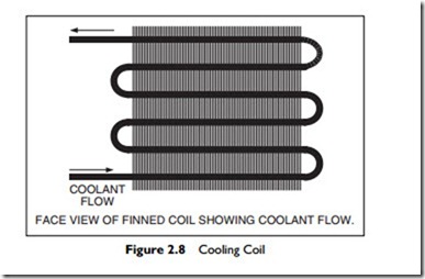
Cooling is most often achieved in an air-conditioning system by passing the moist air over a cooling coil. As illustrated in Figure 2.8, a coil is constructed of a long serpentine pipe through which a cold liquid or gas flows. This cold fluid is either chilled water, typically between 40°F and 45°F, or a refrigerant. The pipe is lined with fins to increase the heat transfer from the air to the cold fluid in the pipe. Figure 2.8 shows the face of the coil, in the direction of airflow. Depending on the coil design, required temperature
drop, and moisture removal performance, the coil may have 2 to 8 rows of piping. Generally the more rows, the higher the moisture removal ability of the coil.
There are two results. First, the cooling coil cools the air as the air passes over the coils. Second, because the cooling fluid in the coil is usually well below the saturation temperature of the air, moisture condenses on the coil, and drips off, to drain away. This process reduces the enthalpy, or heat, of the air mixture and increases the enthalpy of the chilled water or refrigerant. In another part of the system, this added heat must be removed from the chilled water or refrigerant to recool it for reuse in the cooling coil.
The amount of moisture that is removed depends on several factors including:
e The temperature of the cooling fluid
e The depth of the coil
e Whether the fins are flat or embossed
e The air velocity across the coil.
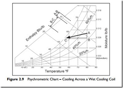
An example of the typical process is shown in Figure 2.9.
The warm moist air comes into the building at 80°F and 50% rh, and passes through a cooling coil. In this process, the air is being cooled to 57°F. As the moisture condenses on the coil, it releases its latent heat and this heat has to be removed by the cooling fluid. In Figure 2.9 the moisture removal enthalpy, A : B, is about a third of the enthalpy required to cool the air, B : C.
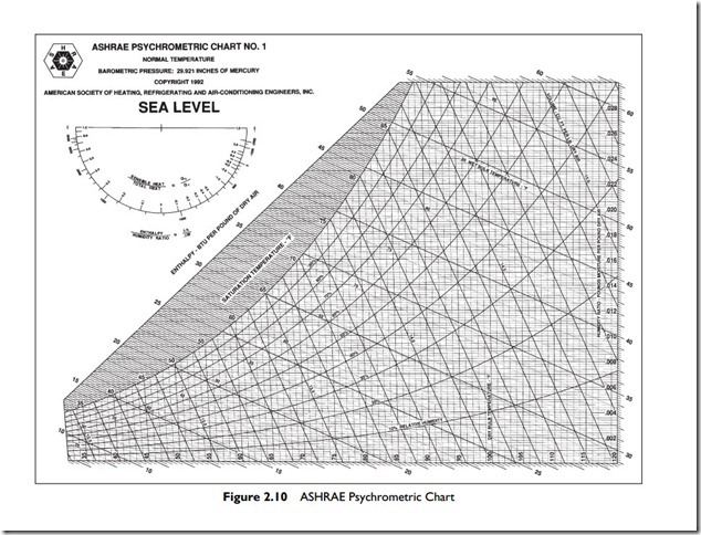
This has been a very brief introduction to the concepts of the psychrometric chart. A typical chart is shown in Figure 2.10. It looks complicated, but you know the simple underlying ideas:
Indoor air is a mixture of dry air and water vapor.
There is a specific amount of total energy, called enthalpy, in the mixture at a specific temperature, moisture content and pressure.
There is a maximum limit to the amount of water vapor in the mixture at any particular temperature.
The actual use of the chart for design, including the calculations, is detailed in the ASHRAE course Fundamentals of Thermodynamics and Psychrometrics1.
Now that we have an understanding of the relationships of dry air, moisture and energy, at a particular pressure we will consider an air-conditioning plant that will provide all seven basic functions of an air-conditioning system to a single space. Remember, the processes required are: heating, cooling, dehumidifying, humidifying, ventilating, cleaning and air movement.
