Basic Air-Conditioning System
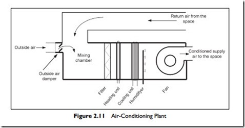
Figure 2.11 shows the schematic diagram of an air-conditioning plant. The majority of the air is drawn from the space, mixed with outside ventilation air and then conditioned before being blown back into the space.
As you discovered in Chapter 1, air-conditioning systems are designed to meet a variety of objectives. In many commercial and institutional systems, the ratio of outside ventilation air to return air typically varies from 15 to 25% of outside air. There are, however, systems which provide 100% outside air with zero recirculation.
The components, from left to right, are:
Outside Air Damper, which closes off the outside air intake when the system is switched off. The damper can be on a spring return with a motor to drive it open; then it will automatically close on power failure. On many systems there will be a metal mesh screen located upstream of the filter, to prevent birds and small animals from entering, and to catch larger items such as leaves and pieces of paper.
Mixing chamber, where return air from the space is mixed with the outside ventilation air.
Filter, which cleans the air by removing solid airborne contaminants (dirt).
The filter is positioned so that it cleans the return air and the ventilation air. The filter is also positioned upstream of any heating or cooling coils, to keep the coils clean. This is particularly important for the cooling coil, because the coil is wet with condensation when it is cooling.
Heating coil, which raises the air temperature to the required supply temperature.
Cooling coil, which provides cooling and dehumidification. A thermostat mounted in the space will normally control this coil. A single thermostat and controller are often used to control both the heating and cooling coil. This method reduces energy waste, because it ensures the two coils cannot both be “on” at the same time.
Humidifier, which adds moisture, and which is usually controlled by a humidistat in the space. In addition, a high humidity override humidistat will often be mounted just downstream of the fan, to switch the humidification “off” if it is too humid in the duct. This minimizes the possibility of condensation forming in the duct.
Fan, to draw the air through the resistance of the system and blow it into the space.
These components are controlled to achieve six of the seven air-conditioning processes.
Heating: directly by the space thermostat controlling the amount of heat supplied by the heating coil.
Cooling: directly by the space thermostat controlling the amount of cooling supplied to the cooling coil.
Dehumidifying: by default when cooling is required, since, as the cooling coil cools the air, some moisture condenses out.
Humidifying: directly, by releasing steam into the air, or by a very fine water spray into the air causing both humidification and cooling.
Ventilating: provided by the outside air brought in to the system.
Cleaning: provided by the supply of filtered air.
Air movement within the space is not addressed by the air-conditioning plant, but rather by the way the air is delivered into the space.
Economizer Cycle
In many climates there are substantial periods of time when cooling is required and the return air from the space is warmer and moister than the outside air. During these periods, you can reduce the cooling load on the cooling coil by bringing in more outside air than that required for ventilation. This can be accomplished by expanding the design of the basic air-conditioning system to include an economizer.
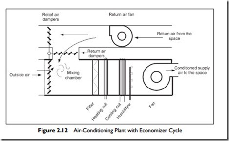
The economizer consists of three (or four) additional components as shown in Figure 2.12.
Expanded air intake and damper, sized for 100% system flow.
Relief air outlet with automatic damper, to exhaust excess air to outside.
Return air damper, to adjust the flow of return air into the mixing chamber.
(Optional) Return fan in the return air duct. The return fan is often added on economizer systems, particularly on larger systems. If there is no return fan, the main supply fan must provide enough positive pressure in the space to force the return air out through any ducting and the relief dampers. This can cause unacceptable pressures in the space, making doors slam and difficult to open. When the return air fan is added it will overcome the resistance of the return duct and relief damper, so the space pressure stays near neutral to outside.
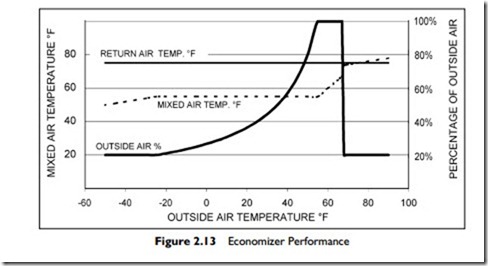
Example: Let us consider the operation of the economizer system in Figure 2.13. The particular system operating requirements and settings are:
The system is required to provide supply air at 55°F Return air from the space is at 75°F Minimum outside air requirement is 20%, Above 68°F, the system will revert to minimum outside air for ventilation.
In Figure 2.13, the outside temperature is shown along the x-axis from -60°F to +100°F. We are going to consider the economizer operation from -50°F up to 100°F, working across Figure 2.13 from left to right.
At -50°F, the minimum 20% outside air for ventilation is mixing with 80% return air at 75°F and will produce a mixed temperature of only 50°F. Therefore, in order to achieve the required supply air at 55°F, the heater will have to increase the temperature by 5°F.
At -25°F, the minimum outside air for ventilation, 20%, is mixing with 80% return air at 75°F to produce a mixed temperature of 55°F, so the supply air will no longer require any additional heating.
As the temperature rises above -25°F the proportion of outside air will steadily increase to maintain a mixed temperature of 55°F. When the outside air temperature reaches 55°F the mixture will be 100% outside air (and 0% return air). This represents full economizer operation.
Above 55°F the controls will maintain 100% outside air but the temperature will rise as does the outside temperature. The cooling coil will come on to cool the mixed air to the required 55°F.
In this example, at 68°F the controls will close the outside air dampers, and allow only the required 20% ventilation air into the mixing chamber.
From 68°F to 100°F the system will be mixing 20% outside air and 80% return air. This will produce a mixture with temperature rising from 73.6°F to 80°F as the outside air temperature rises from 68°F to 100°F.
The useful economizer operation is from -25°F to 68°F. Below -25°F the economizer has no effect, since the system is operating with the minimum 20% outside ventilation air intake. In this example, 68°F was a predetermined change-over point. Above 68°F, the economizer turns off, and the system reverts to the minimum outside air amount, 20%.
The economizer is a very valuable energy saver for climates with long periods of cool weather. For climates with warm moist weather most of the year, the additional cost is not recovered in savings. Also, for spaces where the relative humidity must be maintained above �45%, operation in very cold weather is uneconomic. This is because cold outside air is very dry, and considerable supplementary humidification energy is required to humidify the additional outside air.


