HOT WATER BOILERS
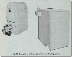
The boilers used in hot water heating systems are made of cast iron or steel (Figs. 21 and 22). The cast iron boilers generally dis play a greater resistance .to the corrosive effects of water than the steel ones do, although the degree of corrosion can be significantly reduced by chemically treating the water.
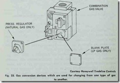
Most hot water heating boilers are designed to burn coal, gas (natural or propane) or oil. Some manufacturers will provide conversion devices for swHching from one type of gas to the other (Fig. 23). Changing from coal to oil or gas is a frequent type of conversion provided for by conversion burners (see Chapter 16. BOILER AND FURNACE CONVERSIONS).
Never purchase an uncertified boiler. All certified boilers are approved by one of several organizations that have assumed this responsibility. For example, many boilers are cer.tified by either the Institute of Boiler and Radiator Manufacturers (cast iron boilers) or the Steel Boiler Institute (steel boilers). They will be stamped “I-B-R” or “SBI” respectively. Fig. 24 illustrates some of the certifications you will encounter on boilers.
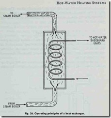
Steam boilers can also be used in hot-water heating systems,but a heat exchanger must be incorporated into the system to transfer the heat from the steam to the hot water that flows through the heat emitting units in the rooms (see HEAT EX CHANGERS in ·this chapter).
HEAT EXCHANGERS
Steam can also be used as a source of heat in a hot-water heating system. If such is the case, then a heat exchanger (Fig.25) must he used to convert the steam to hot water before it reaches the heat emi.Uing units. The heat exchanger is commonly of the steel shell and copper tube design. The steam flows through the shell and the water through the tubes (Fig.26). The hot water returns to the steam boiler where it is reheated and changed to steam again.
CONTROL COMPONENTS
The efficient and safe operation of a hot-water heating system requires the use of a variety of different ·types of controls, which can be roughly divided into either system actuating controls (e.g. the room thermostat, burner controls, circulating pump controls, etc.) or safety controls (e.g. high-limit controls, pressure-relief valve, pressure reducing valve, etc.)
The safety controls prevent damage to the system by shutting it down when pressure and temperature levels become excessive. The high-limit control or aquastat is an example of such a control. It is a device designed to operate in conjunction with ·the circulating pumps and is located on the hot water boiler. If .the pressure or temperature of the hot water exceeds ·the design limits of the system, the system is shut down until conditions return to an acceptable level. Some aquastat relays provide multizone control when used with a separate circulator and a relay for each zone.
Another very important safety control for hot-water heating systems, is the pressure relief valve. These valves are designed to open when pressure in the boiler reaches a certain level and close when ‘the pressure returns to a safe level again. Pressure relief valves must be installed in accordance with current A.S.M.E. or local codes.
These and other types of controls (e.g. main shutoff valves, pressure-reducing valves, drain cocks, etc.) are described in con siderable detail in a number of different chapters in this book, including: Chapter 15 (BOILERS AND BOILER FITTINGS),
. Chapter 4 (THERMOSTATS AND HUMIDISTATS), and Chap ter 9 of Volume 2 (VALVES AND VALVE INSTALLATION).
PIPES AND PIPE SIZING
Pipes and pipe sizing methods are described in considerable detail in Chapter 8, Volume 2 (PIPES, PIPE FITTINGS, AND PIPING DETAILS).
The selection of pipe used in hot-water heating systems depends primarily upon the following two factors: ( 1) the flow rate of the water and (2) the friction loss in the pipes. The flow rate of the water is measured in gallons per minute (gpm), and constant friction loss is expressed in thousandths of an inch for each foot of pipe length.
EXPANSION TANKS
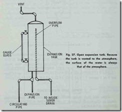
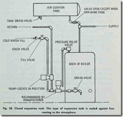
Expansion tanks (Figs. 27 and 28) are installed in hot-water heating systems to provide for the expansion and contraction of the water as it changes in temperature. Water expands with the rise of temperature, and the excess volume of the water flows into the expansion tank.
Another feature of the expansion tank is that the boiling point of the water can be increased by elevating the tank. In other
words, increasing .the head (i.e. the difference in elevation between two points in a body of fluid) increases the pressure. As a result, the water can be heated to a higher temperature without gen erating steam which in .turn causes the radiators or other heat emitting devices to give off more heat.
There are both open and closed types of expansion tanks used in hot-water heating systems. The open expansion tank is used on low pressure systems and the closed tank on high pressure systems; air in the tank above the water forms a cushion for increasing the pressure. As the temperature of the water rises, it expands and flows into the •tank, thus compressing the air and increasing the pressure.
The relation between pressure and volume changes of the air should be understood. According to Boyle’s Law, at constant
temperature the pressure of a gas varies inversely as its volume. Thus, when the volume is reduced to half, the pressure is doubled. This is not gauge pressure, but absolute pressure (the pressure measured from true zero or point of no zero pressure).
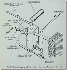
In gravity hot-water heating systems, either closed or open piping arrangements can be used. In an open gravity system, the expansion tank is located at the highest point in the system (e.g. roof, attic, •top floor, etc.) (Fig. 29). The expansion tank used in this piping arrangement is an open type with an overflow pipe located at .the top. Provisions can be made ·to return the overflow water to the boiler or to discharge it through outside run-off drains.In a closed gravity system, a closed, airtight expansion tank is located near the hot-water boiler. Higher pressures (and, consequently, higher water temperatures) result as pressure builds up in the system. Pressure relief valves are installed on the main supply line to prevent the buildup of too much pressure.
Forced (hydronic) hot-water heating systems are closed systems with expansion tanks located near the boiler.
