Pressure controls
There are many different makes of pressure controls. Designs may vary but the principle of operation is basically the same: single pressure models respond to either low or high pressure; dual pressure versions can be activated by both high and low pressures.
Pressure controls are installed to perform a variety of functions. Most current production controls are designed with three electrical terminals. These enable the control to be used to open an electrical circuit upon a rise in pressure or upon a fall in pressure, depending on the application. Unfortunately, identification of the electrical terminals is not standard, and it is important to know which of the three is the common terminal.
Single pressure controls have two adjusting screws: the range and the differential. Dual pressure versions have three screws: the range and differential for low pressure operation, and a range screw for high pressure operation. This differential is preset at 50 psi or 3.5 bar.
The controls described are commonly employed and will serve to identify adjusting screws and electrical terminals.
Applications
A low pressure control may be used as:
1 A temperature control.
2 A safety cut-out to prevent overcooling or overfreezing of a product.
3 A defrost termination control to open the circuit to defrost heaters should the evaporator become completely free of frost before the defrost period has elapsed. This prevents undue pressure build-up in the evaporator.
4 A compressor cut-out when operating on a pump-down cycle.
An evaporator fan delay control to prevent warm air and moisture from being circulated to the refrigerated space after defrost.
A high pressure control is employed as a safety cut-out for the compressor in the event of excessive operating pressures developing on the high side of the system during operation. Table 4 shows the settings required.
Example controls
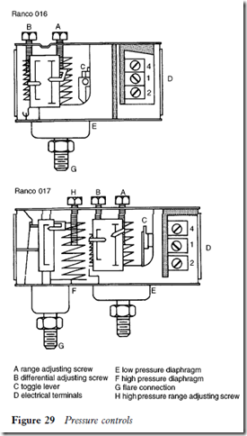
Figure 29 shows two typical controls. The details are as follows.
To complete an electrical circuit on rise in pressure, terminals 1 and 4 must be used. To complete an electrical circuit on fall in pressure, terminals 1 and 2 must be used.
The control range is 12 in Hg vacuum to 100 psi (0.4 to 7 bar).
The control range is 12 in Hg vacuum to 100 psi (0.4 to 7 bar) on the low pressure side, and 100 to 400 psi (7 to 26.5 bar) on the high pressure side. The high pressure automatic reset differential is 50 psi (3.5 bar).
Control setting procedure
For low pressure control:
1 Adjust the range screw A until the compressor cuts in at the selected pressure.
2 Adjust the differential screw B to stop the compressor at the desired cut-out pressure.
For high pressure control, adjust the range screw H to a selected cut-out pres- sure and the control will reset automatically.
Check the control operation several times after final adjustments have been made.
Always adjust controls with a pressure gauge, using the graduated scales as a guide only. Never lever the control mechanism to actuate it; this can
damage the pivot and cause erratic operation or failure. Use the insulated lever if fitted.
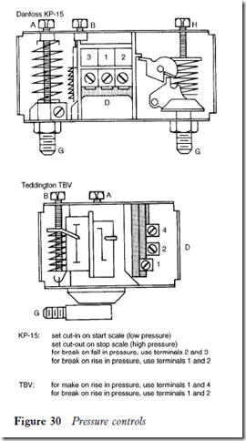
This procedure can be followed for setting any make of control, such as those in Figure 30.
When locking plates are provided, set the control, replace the locking plate to secure the differential screw, and fit the knob to the range screw.
Low pressure control adjustments can be made by front seating the suction service valve to reduce the pressure on the low side of the system.
High pressure control adjustments must be made by increasing the oper- ating head pressure, i.e. by blocking off the condenser, thereby restricting the air flow, or by switching off condenser-fans. The head pressure can be quickly increased on water cooled units by shutting off the water supply.
It is dangerous practice to increase the head pressure by front seating the discharge service valve.
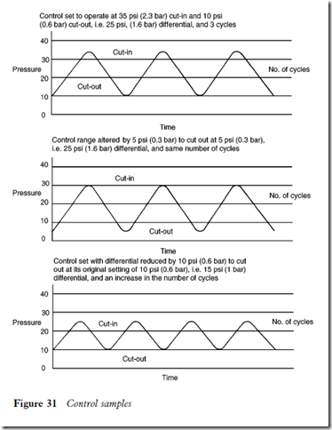
Control examples
The examples in Figure 31 illustrate the effects of a reduced range and differ- ential setting with a low pressure control.


