Light-Emitting Diodes (LEDs) and Photodiodes
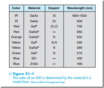
Light-emitting diodes (LEDs) are among the most common devices found in the electrical and electronics fields. They are used as indicator lights in many types of equipment. They have an extremely long life when operated within their ratings because there is no filament to burn out. LEDs are constructed by joining special semiconductor materials together that emit photons when power is applied. The color produced is determined by the types of materials used. LED colors are generally IR (infrared), red, green, yellow, orange, and blue. The basic light- emitting diode is formed by joining gallium arsenide (GaAs) or gallium phosphide (GaP) with some other material. These two solutions can be combined to form a solid solution known as gallium arsenide phosphide (GaAsP). Different colors are produced by adding other compounds, called dopants, such as zinc selenide (ZnSe) or silicon carbide (SiC). The
chart in Figure 51–1 shows different-colored LEDs, the wavelength of light in nanometers, and the materials used to construct the diode.
LED CHARACTERISTICS
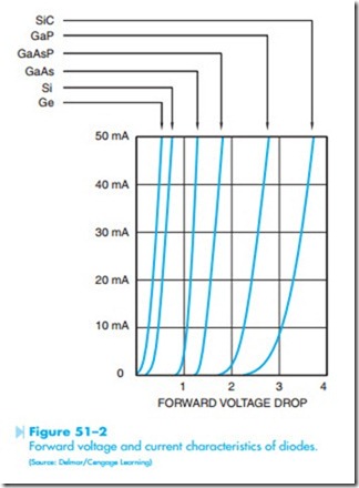
The electrical characteristics of light-emitting diodes vary considerably from those of the common junction or rectifier diode. Junction diodes have a for- ward voltage drop of about 0.7 volts for silicon and
volts for germanium. LEDs have a forward volt- age drop of about 1.7 volts or greater, depending on the material the diode is made of. Most light-emitting diodes are operated at about 20 mA or less current. A chart showing the typical forward voltage drop of different diodes is shown in Figure 51–2. Junction diodes typically have a PIV rating of 100 volts or greater, but LEDs have a typical PIV rating of about 5 volts. For this reason, when light-emitting diodes are used in applications where they are intended to block any amount of reverse voltage they are connected in series with a junction diode.
Testing LEDs
Light-emitting diodes can be tested in a manner similar to that of testing a junction diode. The LED is a rectifier and should permit current to flow through it in one direction only. When testing an LED with an
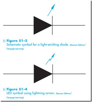
ohmmeter, it must be capable of supplying enough voltage to overcome the forward conduction voltage of about 1.7 volts or higher. The meter, however, must not supply a voltage that is higher than the reverse breakdown voltage. The schematic symbol for a light-emitting diode is shown in Figure 51–3. Some symbols use a straight arrow as shown in Figure 51–3, and others use a lightning arrow as shown in Figure 51–4. The lightning arrow symbol is employed to help prevent the arrow from being confused with a lead attached to the device. The important part of the symbol is that the arrow is pointing away from the diode. This indicates that light is being emitted or given off by the diode.
LED Lead Identification
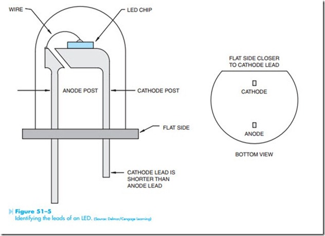
Light-emitting diodes are housed in many different case styles. Regardless of the case style, however,
there is generally some method of identifying which lead is the cathode and which is the anode. The case of most LEDs will have a flat side that is located closer to the cathode lead, Figure 51–5. Also, the cathode lead is generally shorter.
Seven-Segment Displays
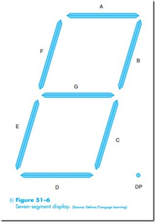
A very common device that employs the use of light-emitting diodes is the seven segment display, Figure 51–6. The display actually contains eight LEDs, each segment plus the decimal point. Common cathode displays have all the cathodes connected together to form a common point. The display is energized by connecting a more positive voltage to the anode lead of each segment. Common anode dis- plays are energized by connecting the appropriate cathode lead to a more negative voltage (generally ground). The seven-segment display can be used to display any number from 0 to 9.
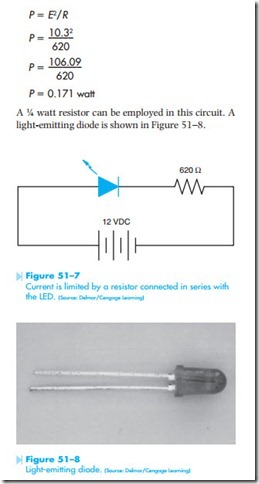
The minimum power rating for the resistor can also be determined using Ohm’s law. The LED will have a voltage drop of approximately 1.7 volts. Because the resistor is connected in series with the LED, it will have a voltage drop of 10.3 volts.
F The power dissipation of the resistor can now be
C A ¼ watt resistor can be employed in this circuit. A light-emitting diode is shown in Figure 51–8.
Connecting the LED in a Circuit
When used in a circuit, the LED generally operates with a current of about 20 mA (0.020 A) or less. Assume that an LED is to be connected in a 12-VDC circuit and is to have a current draw of approximately 20 milliamperes. This LED must have a current-limiting resistor connected in series with it. Ohm’s law can be used to determine what size resistor should be connected in the circuit.
The nearest standard size resistor without going below 600 Ω is 620 Ω. A 620 Ω resistor would
