PRESSURE CONTROLLERS
When the room thermostat calls for heat in a steam heating system, the electrical current flows to the operating controls of the automatic fuel burning equipment (oil burner, gas burner, or coal stoker) through a high-limit switch. In a steam boiler con trol system, the high-limit switch is activated by pressure, and is referred to as a pressuretrol.
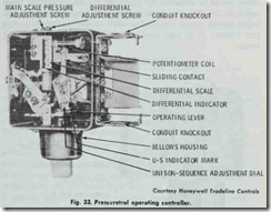
Fig. 33 shows a pressuretrol operating controller which is designed to provide on-off and proportional control of steam boil ers fired by proportional type burners. It can be field adjusted to operate either in unison (burner starts at high fire), or in se quence (burner starts at some firing rate other than high fire). A common bellows assembly located in the bellows housing actuates the stop-start snap switch (on-off operation) and the wiper of the 185 ohm potentiometer (proportional operation).
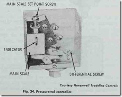
The pressure controller shown in Fig. 34 operates strictly as a high limit pressure safety control on steam heating boilers. It
breaks the electrical circuit on pressure rise. A variation of this controller (the Honeywell PA404B Pressuretrol Controller) is used for suspension type unit heaters.
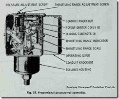
Direct control for a proportional motor operating an auto matic burner is obtained by using the pressure controller illus trated in Fig. 35. This unit contains two potentiometers operat ing in unison, which makes it possible to simultaneously control two motors. It is also provided with an adjustable throttling range.
Pressure controllers are also available for vapor or vacuum systems. A pressure controller with a bellows operated mercury switch is manufactured by Honeywell for use on vapor heating systems with pressures up to 4 psi. The pressure controller illus trated in Fig. 36 can be used as a boiler high-limit control with cut-in and cut-out settings in the vacuum range. In such installa tions, the heating system must include a vacuum pump and a siphon loop.
LOW-WATER CUTOFFS
Steam boilers must be provided with a water level control de vice that will shut off the automatic fuel burning equipment when the water level in the boiler drops to a level too low for safe oper ation. This water level control device is referred to as a low-water cutoff. The two types of low-water cutoffs used on steam boilers are the float type and the probe type.
A float type low-water cutoff device consists of a cutoff switch operating in conjunction with a float located in the boiler water or in a float chamber installed next to the boiler. The float is connected through a linkage to a switch which operates a feed water valve. As the water level falls, the float drops with it until it reaches a point at which the feed water switch is actuated. If the water level continues to fall, a second switch connected to the float by the linkage is actuated and the automatic fuel burning equipment is shut off.
A probe type low-water cutoff device depends on the flow of a low electrical current to control the operation of the automatic fuel burning equipment. The electrical current flows from the probe through the water to keep the relay energized. When the water level falls, there will be a point at which the probe loses direct contact with the water. As a result, the contact is broken and the flow of the electrical current is stopped. This, in turn, causes the relay to be energized, which results in shutting off the fuel burning equipment. A probe type low-water device cannot be used in the direct operation of feed water valves.
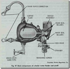
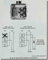
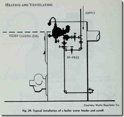
On some boilers, the low-water cutoff is combined with a water feeder to add water to the boiler when the water level falls below the safe operating limit. An example of one of these combined units is shown in Fig. 37. They are available with either single or dual switch assemblies. The single double-throw switch assembly provides a combination feeder and burner cutoff switch with an extra terminal for line voltage with single-pole double throw service (Fig. 38). The dual switch assembly is used for line voltage burner service and for independent low (or high) voltage alarm, feed valve or pump starter service. When an emergency condition occurs, the switch interrupts the current to the burner and shuts it off. When the emergency has passed, the water feeder takes over and feeds make-up water when needed for normal op eration. On units equipped with dual switch assemblies, the alarm, feed valve or pump starter switch actuates just before the burner switch cuts the firing. A typical installation of a Watts 60 LWD boiler water feeder and cutoff on a steam boiler is illus trated in Fig. 39.
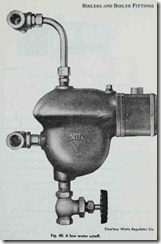
A low-water cutoff without a boiler water feeder is usually adequate for providing automatic low water safety protection for most small boilers (Fig. 40). These units can be installed on any boiler having gauge glass connections.
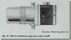
Direct installation type low-water cutoffs are available for boilers with limited space in the boiler jacket (Fig. 41). Each unit contains a switch assembly and float, and is screwed into the boiler through a 2V2 inch tapping.
INSTALLING A LOW WATER CUTOFF
The Watts No. 89 low-water cutoff illustrated in Fig. 40 is suitable for low pressure steam heating boilers with a maximum operating steam pressure of 15 lbs. Although installation is rela tively simple, the instruction s should be carefully followed. This is a boiler safety device, and it must operate properly or the boiler can be damaged.
Before installing the Watts low-water cutoff, the gauge glass and cocks must be removed from the boiler. When you have done this, proceed as follows:
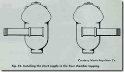
Install the V2 inch tee (with long and short nipples) on the float chamber by inserting the short nipple in the float chamber tapping in the end opposite the switch. Screw the tee tight with the long nipple pointing in the correct direction, depending on the location of the boiler. (Fig. 42).
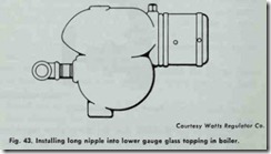
2. Insert the long nipple into the lower glass gauge tapping on the boiler.
3. Swing the entire float chamber until the nipple is made up tight. Line up the cutoff so that the top of the switch box is level (Fig. 43).
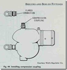
4. Screw the nipple in the tee carrying the tubing connector into the upper gauge glass tapping and pull up tight. Install a compression coupling in the top float chamber tap ping (Fig. 44).
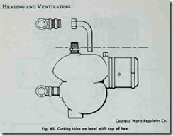
5. Hold the tube bend in position and mark the tube on a level with the top of the hex on the compression coupling. Cut off the tube at this mark (Fig. 45).
6. Slide the ring and nut over the end of the connector tube.
7. Slide the end of the tube into the compression coupling in the float chamber, and tighten both couplings.
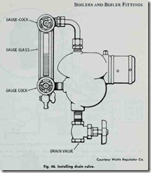
8. Install a drain valve in the bottom float chamber tapping (Fig. 46).
9. Reinstall the gauge cocks in the end of the tees and re place the gauge glass (Fig. 46).
The drain valve should be opened at least once every month (or oftener) during boiler operation to flush out sediment from the float chamber.
