The diffuser system
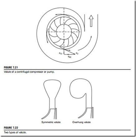
Centrifugal compressors and pumps are, in general, fitted with either a vaneless or a vaned diffuser to transform the kinetic energy at the impeller outlet into static pressure. The volute or scroll is the final component of a centrifugal compressor or pump (Figure 7.21). This is a spiral-shaped channel of increasing cross-sectional area whose purpose is to collect the flow from the diffuser (or impel- ler) and deliver it to the exit pipe. The volute for compressors is almost always of the overhung type, usually the choice is imposed by constraints of space. Figure 7.22 shows two types of volute cross section.
According to Whitfield and Johnson (2002), it is well known that the volute of a centrifugal compressor can cause a circumferential pressure distortion around the impeller at all flow rates other than at design.
Vaneless diffusers or volutes
The simplest method of diffusion in a radial flow machine is one where the swirl velocity is reduced by an increase in radius (conservation of angular momentum) and the radial component of velocity is controlled by the radial flow area. From continuity, since m_ 5 ρAcr 5 2πrbρcr; where b is the width of passage, then the radial velocity cr at radius r is
Assuming the flow is frictionless in the diffuser, the angular momentum is constant and cθ 5 cθ2r2/r. Now the tangential velocity component cθ is usually very much larger than the radial velocity component cr; therefore, the ratio of inlet-to-outlet diffuser velocities c2/c3 is approximately r3/r2. Clearly, to obtain useful reductions in velocity, volutes must be large. This may not be a disadvantage in industrial applications where weight and size may be of secondary importance compared with the cost of a vaned diffuser. A factor in favor of volutes is their wide operating range, vaned diffusers being more sensitive to flow variation because of incidence effects.
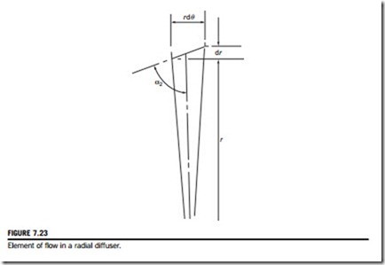
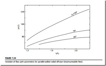
For a parallel-walled radial diffuser in incompressible flow, the continuity equation requires that rcr is constant. Assuming that rcθ remains constant, then the absolute flow angle α2 5 tan21ðcθ=crÞ is also constant as the fluid is diffused outward. Under these conditions, the flow follows a logarithmic spiral. The relationship between the change in the circumferential angle Δθ and the radius ratio of the flow in the diffuser can be found by considering an element of the flow geometry, shown in Figure 7.23. For an increment in radius Dr we have, rdθ 5 Dr tan α2. Integrating between stations 2 and 3, gives
Values of Δθ are shown in Figure 7.24 plotted against r3/r2 for several values of α2. It can be readily seen that when α2 . 70o, rather long flow paths are implied, friction losses will be greater
and the diffuser efficiency will be lower. Further information about volute design and testing can be found in a paper by Whitfield and Johnson (2002).
Vaned diffusers
With vaned diffusers, the vanes are used to remove the swirl of the fluid at a higher rate than is possible by a simple increase in radius, thereby reducing the length of flow path and diameter. The vaned diffuser is clearly advantageous where small unit size is important.
There is a clearance between the impeller and the vane leading edges amounting to about 0.04D2 for pumps and between 0.1D2 and 0.2D2 for compressors. This space constitutes a vaneless diffuser and its functions are (i) to reduce the circumferential pressure gradient at the impeller tip, (ii) to smooth out velocity variations between the impeller tip and the vanes, and (iii) for compressors, to reduce the Mach number at entry to the vanes. Flow calculations in this space follow the same procedure as for vaneless diffusers.
The flow follows an approximately logarithmic spiral path to the vanes after which it is con- strained by the diffuser channels. For rapid diffusion, the axis of the channel is straight and tangential to the spiral as shown. The passages are generally designed on the basis of simple channel theory with an equivalent angle of divergence of between 8o and 10o to control separation.
In many applications of the centrifugal compressor, size is important and the outside diameter must be minimized. With a vaned diffuser, the channel length can be crucial when considering the final size of the compressor. Clements and Artt (1988) considered this and performed a series of experiments aimed at determining the optimum diffuser channel length to width ratio, L/W. They found that, on the compressor they tested, increasing L/W beyond 3.7 did not produce any improvement in the performance, the pressure gradient at that point having reached zero. Another significant result found by them was that the pressure gradient in the diffuser channel when L/W . 2.13 was no greater than that which could be obtained in a vaneless diffuser. Hence, removing completely that portion of the diffuser after this point would yield the same pressure recovery as with the full diffuser.
The number of diffuser vanes can also have a direct bearing on the efficiency and surge margin of the compressor. Surge occurs at higher flow rates when vaned diffusers are used than when a simple vaneless diffuser design is adopted. It is better to have fewer diffuser vanes than impeller vanes (about half) in order to achieve a wide range of surge-free flow.
With several adjacent diffuser passages sharing the gas from one impeller passage, the uneven velocity distribution from that passage results in alternate diffuser passages being either starved or choked. This is an unstable situation leading to flow reversal in the passages and to surge of the compressor. When the number of diffuser passages is less than the number of impeller passages a more uniform total flow results.
Figure 7.9 shows the occurrence of flow unsteadiness or nonuniform flow at the exit from 2D diffusers. The line marked a-a will be of most interest for turbomachinery diffuser applications.
Note that this sharply marked transition line is not necessarily true and exact and a certain amount of arbitrariness and subjectivity attends the occurrence of “first stall.”
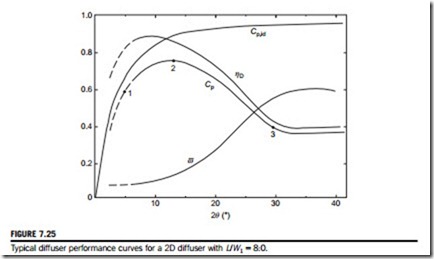
Figure 7.25 shows typical performance curves for a rectangular diffuser with a fixed sidewall to length ratio, L/W1 5 8.0, given by Kline, Abbott, and Fox (1959). On the line labeled Cp, points numbered 1, 2, and 3 are shown. These numbered points correspond to those shown in Figure 7.9 where they lie in relation to the various flow regimes. Inspection of the location of point 2 shows that optimum recovery at constant length occurs slightly above the line marked No appreciable
stall. The performance of the diffuser between points 2 and 3 in Figure 7.9 shows a very significant deterioration and is in the regime of large amplitude, very unsteady flow.


