Pilot-Pressure Switch
A pilot-pressure switch operates on the same principle as the gas- pressure switch used in the manifold of the gas-fired furnace or boiler. Its function is to prevent the premature failure of the spark igniter or glow coil should a prolonged gas interruption occur while the thermostat is calling for heat.
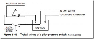
The pilot-pressure switch is installed in the pilot gas line between the pilot and pilot regulator. Installing a pilot switch requires that the pilot gas line be disconnected downstream from the pilot gas regulator. The gas line is then connected to the pilot-pressure switch by cutting the existing tubing to the regulator and connecting into the tee provided for switch mounting. A typical wiring of a pilot- pressure switch is shown in Figure 5-63.
Electronic Ignition Modules
Electronic (solid-state) ignition systems have been developed to improve the energy efficiency of gas furnaces, boilers, and water heaters. These electronic ignition systems replace the less energy-efficient standing pilot used in traditional gas-fired appliances. There are three different types of controls used in electronic ignition systems:
• Intermittent pilot ignition module
• Direct ignition gas module
• Hot-surface ignition module
Note
Ignition modules do not have replaceable parts. If defective, the entire unit must be replaced. A replacement module must be of the exact same model and type as the defective one.
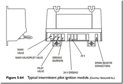
Manufacturers of electronic ignition modules offer a wide range of models designed to fit a variety of different applications (see Figure 5-64). Always make certain that the make, model, and operating specifications of the original gas valve control module match those of the replacement one. Specification sheets and installation instructions for electronic ignition modules are available online at the manufacturer’s Web site or by writing directly to the manufacturer (see Appendix B for contact information).
The following three sections briefly describe the three types of electronic ignition modules used in gas-fired furnaces, boilers, and water heaters. For more detailed and model-specific information, consult the owner’s manual, installation manual, and/or the specifi- cation/data sheets provided by the manufacturer.
Intermittent Pilot Ignition Module
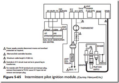
An intermittent pilot ignition module is a solid-state ignition device used to automatically light a pilot burner and simultaneously energize (operate) the main gas valve of the heating system when the room
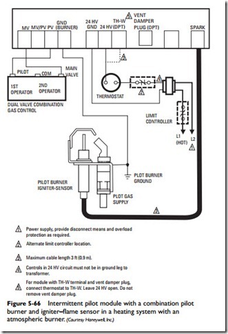
thermostat calls for heat (see Figure 5-65). Figure 5-66 illustrates the wiring connections between an intermittent pilot module, the dual- valve combination valve, and the combined pilot burner and igniter- sensor unit.
The operating sequence for a gas burner operated by an inter- mittent pilot ignition control is as follows:
1. thermostat calls for heat, and the intermittent pilot ignition module simultaneously opens the pilot valve and sup- plies a continuous spark to the electrode in the pilot burner.
2. burner gas ignites and produces a flame.
3. flame sensor detects the pilot flame and signals the intermittent pilot ignition control to discontinue the spark and energize (open) the main gas valve.
Note
The main gas valve will not be energized until the flame sensor detects the presence of the pilot flame. As long as the main gas valve remains closed, no gas from the supply line can flow through the burners. Should a loss of flame occur, the main gas valve closes and the spark recurs within 0.5 second.
4. from the gas supply line flows through the now-open main gas valve to the burners and ignites. This is the burn or on cycle. When the heat has reached the level required by the thermostat setting, the main gas closes and the burner or burners shut down. This is the off cycle in an intermittent pilot ignition control system.
Some Useful Definitions
• Run—The period during which the main gas valve remains energized and the spark is turned off after the successful ignition.
• Trial for ignition—The period during which the pilot valve and spark are activated, attempting to ignite gas at the main gas burner.
• Flameout—The loss of proven flame.
• Proven flame—A pilot flame detected by a flame sensory device.
• On cycle—Period of time during which the main gas valve is open and the burners are operating.
• Off cycle—Period of time during which the main gas valve is closed and the burners are not operating.
If the pilot flame is extinguished, even though the room thermo- stat is still calling for heat, the intermittent pilot ignition control immediately deenergizes the main gas valve, causing it to close its open supply port and stop the flow of gas to the burners. A spark at the pilot burner electrode will recur within 0.8 second.
As soon as the pilot flame is reignited and detected by the pilot flame sensor, the main gas valve is energized, the valve port is opened, and the spark is extinguished. The intermittent pilot ignition control then deenergizes the pilot gas and main burner gas valve when the thermostat stops calling for heat.


