TROUBLESHOOTING WITH THE VOLTMETER
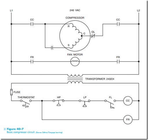
Before it is possible to troubleshoot a circuit, the technician must have an understanding of how the circuit operates normally. The circuit shown in Figure 40–7 is a basic control circuit for a compressor. The circuit operates as follows:
1. When the thermostat contacts close, power is provided to the FR (fan relay) coil.
2. This causes both FR load contacts to close and connect the fan motor to the 240-volt line.
3. The moving air of the fan causes flow switch FL to close.
4. When switch FL closes, power is provided to the compressor contactor (CC).
5. Both CC load contacts close and supply power to the compressor motor.
6. High-pressure and low-pressure switches connected in series with the compressor contactor provide protection for the compressor.
7. When the thermostat opens, the circuit to both the compressor contactor and fan relay is broken disconnecting the compressor and fan from the line.
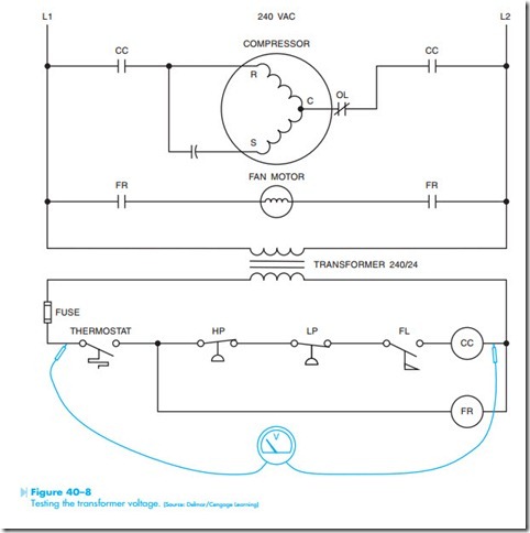
Assume that a problem has developed with the unit. The service technician is told that the air conditioner will not work. The first test to be made is to determine if control voltage is available from the secondary of the transformer. This can be done by checking for 24 volts from the thermostat to CC, Figure 40–8. For the purpose of this example, it will be assumed that the voltmeter indicated 24 volts.
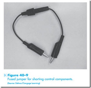
The next step is to attempt to operate the unit. Many service technicians use a jumper to short the thermostat contacts. When a jumper is used to short components in a control circuit, a fused jumper
is recommended, Figure 40–9. The jumper contains a small amp value fuse such as 3 or 4 amperes. If the jumper should be accidentally connected across power, the fuse will blow instantly. Assume then that the thermostat was jumped; the fan motor started but the compressor did not.
The next step is to determine what could be the problem. Looking at the schematic, make mental notes of what could cause the compressor not to start.
1. CC contactor is defective.
2. Flow switch FL did not close.
3. The low-pressure switch, LP, is open.
4. The high-pressure switch, HP is open.
5. CC load contacts are burned out and not con- necting power to the compressor.
6. The compressor overload is open.
7. The compressor start capacitor is bad.
8. The compressor motor is bad.
The next logical step is probably to determine if voltage is being applied to the coil of the compressor contactor. This can be done by jumping the thermo- stat and checking across CC coil with a voltmeter, Figure 40–10.
For this example, it will be assumed that the volt- meter indicated that there was no voltage applied to contactor coil CC.


