Description
This chapter is devoted to the electrical aspects of hermetic and semi-hermetic motor compressors and remote-drive motors employed in commercial refrigeration and in domestic refrigerators and freezers for single-phase 240 volt 50 hertz supply.
The smaller hermetic compressors are mainly used for domestic systems. Larger capacity units are to be found in coldrooms, refrigerated display counters and display cases. These compressors are supplied in various sizes and designs; some operate with a reciprocating action, others are rotary types.
The starting devices for these single-phase compressors are described and their operation is explained, with test procedures which are the same for both hermetic and semi-hermetic compressors.
Open-type reciprocating compressors are also employed for the commercial range. The starting device for remote single-phase drive motors is included, since the test procedures are again basically the same.
Drive motors and starter contactors for both single and three-phase supply are dealt with in Chapter 15.
The split phase motors employed can be capacitor start for low starting torque, and capacitor start and run for high starting torque, on a 200/240 volts 50 hertz supply.
Different types of starting device are used: the current relay for low starting torque, and the potential (voltage) relay for high starting torque. A form of solid state device may be used for either. Regardless of type, each will have overload protection. There will be three external terminals to which the compressor controls are connected to complete the circuit to the two motor windings. The three compressor terminals are known as common, start and run (C, S and R).
External overload protectors are both current and temperature sensitive; they are easily replaced. Internal overload protectors tend to be less current sensitive and provide better motor protection, but cannot be replaced; this means that correct diagnosis of a fault is imperative.
Of the two motor windings, the main or run winding is the larger in both physical size and cross-section. The other is the start or auxiliary winding. They are both conductors, but current will flow freely through the larger winding and meet resistance in the smaller winding.
Service equipment
To carry out an efficient service and diagnosis, the engineer will require the following instruments: voltmeter, ammeter, ohmmeter (or a multitester), wattmeter, test cord and (not essential) capacitor tester.
The wattmeter is used in conjunction with the manufacturer’s data or that given on the compressor nameplate. Power readings are an aid to diagnosing faults in much the same way as operating head pressures are for open-type compressors. For example, the average running watts are generally provided on the nameplate or model identification plate. Manufacturers’ service manuals will give starting watts, running watts and current consumption under specified conditions for each model.
Current relay
This can best be described as a magnetic switch. It comprises a small solenoid coil around a sleeve and an iron core. Inside the sleeve is a plunger to which the switch contact bridge is attached; the contacts are normally open.
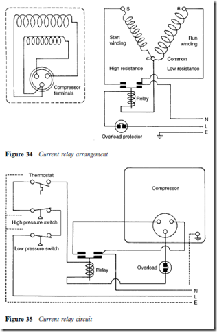
When the coil is energized, a strong magnetic field of force is created because the current will be high during the starting phase. The magnetic force will move the plunger upwards and bridge the switch contacts, completing the circuit to the start winding. The run winding is wired through the relay so that it is always in circuit. Figure 34 shows a typical motor and control arrangement for a current relay, and Figure 35 shows the completed relay circuit.
A high starting current is drawn when the compressor motor starts. The current reduces as the motor gathers speed; the magnetic field through the relay then becomes weaker so that it can no longer hold the contact bridge on to the switch contacts. The plunger then drops down by gravity to open the circuit to the start winding.
It is not uncommon for a start capacitor (see later) to be fitted when a current relay is employed. This is wired in series with the start winding (Figure 36).
