Zoning a Forced-Warm-Air Heating System
The design of some residences, particularly the larger split-level homes, often causes balancing problems for the heating system. As a result, certain rooms will remain much colder than the rest of the house. This is a problem that cannot be corrected simply by turning up the heat, because the rest of the house will become too hot. The most effective solution is to divide the heating system into two separate zones, each controlled by its own thermostat. A motorized damper is installed in the existing duct system and is regulated by thermostats to obtain the balance.
Balancing a Warm-Air Heating System
It is not always necessary to go to the expense of zoning to ensure that each room receives enough heat. Sometimes a heating system can be balanced by reducing the air delivery to rooms or sections of the structure that require less heat. This results in automatically diverting more air and heat to those areas that require it.
The procedure for balancing a warm-air heating system is as follows:
1. Pick a day for balancing the system when the outdoor dry- bulb temperature is 40°F or below.
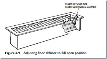
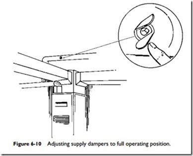
2. Open the dampers in all warm-air outlets as widely as possible (Figure 6-9). The same holds true if the dampers are in the supply ducts (Figure 6-10).
3. Leave the thermostat at one setting for at least 3 hours, and make certain the furnace blower is running.
4. Check the temperatures in all rooms. This can be done with thermometers (if you are certain they register equally), or simply by making your own judgment.
5. Leave the dampers in the coldest rooms wide open, and adjust the dampers in the warmer rooms to obtain the desired balance. After each adjustment, allow the system to stabilize for at least 30 minutes before checking the temperature or making the next adjustment.
When balancing a heating system, do not expect immediate results. A little patience makes it well worth the effort.
Warm-Air Furnaces
The warm-air furnace is a self-contained heating unit designed to sup- ply warm air to the interior of a structure. Warm-air furnaces used in central heating systems usually employ a system of ducts to distribute the air to the various rooms and spaces within the structure.
These furnaces can be classified according to the method of air circulation into the following two basic categories: (1) gravity warm-air furnaces, and (2) forced-warm-air furnaces. A distinct advantage of the forced-warm-air furnace is that its blower can move the air in any direction. As a result, this type of furnace can be located anywhere in the structure. Furthermore, the ducts do not have to be located above the heating unit, as is the case with gravity warm-air furnaces. These advantages of the forced-warm-air fur- nace have contributed to its tremendous popularity over gravity- type furnaces. Both types are described in considerable detail in Chapter 10, “Furnace Fundamentals.”
Other criteria used for classifying warm-air furnaces include:
(1) the type of fuel used (e.g., gas, oil, coal, or electricity), (2) the method of air distribution (ducts or pipeless), and (3) the method of firing (automatic or manual). Specific chapters in this book deal individually with some of these criteria (e.g., Chapter 11, “Gas Furnaces,” or Chapter 12, “Oil Furnaces”).
Control Components
The controls used in a warm-air heating system will depend upon a number of factors, including: (1) the method of air circulation used (e.g., forced or gravity), (2) the size of the structure, and (3) the method used for supplying the fuel (automatic or manual) to the fire. In other words, for all intents and purposes, a control system is custom designed to fulfill the requirements of a specific heating system.
All gravity and forced-warm-air furnaces in central heating systems are controlled by a thermostat located in one of the rooms. If the heating system is zoned, two or more room thermostats are used. In forced-warm-air systems equipped with automatic burners or strokers, the thermostat will also control the operation of these units.
Each furnace should be equipped with a high-limit control to shut off the air or gas burned when plenum air temperatures exceed the furnace manufacturer’s design limits. The high-limit control is automatic and will switch on the burner again as soon as the air temperature in the plenum has returned to normal (i.e., reached a level below the manufacturer’s design limits). The high-limit con- trol is frequently designed to operate in conjunction with the fan (blower) switch in forced warm-air furnaces.
Other controls used in warm-air heating systems are described in Volume 2—Chapter 4, “Thermostats and Humidistats,” Chapter 5, “Gas and Oil Controls,” and Chapter 6, “Other Automatic Controls.”
Ducts and Duct Sizing
Ducts are passageways used for conveying air from a furnace or cooling unit to the rooms and spaces within a structure. The duct- work is also used to return the air to its source for recirculation.
The air is distributed to the rooms or spaces by means of grilles, registers, and diffusers. The size and location of the supply-air out- lets and the return-air inlets are determined by such design factors as: (1) use (heating and cooling), (2) air velocity, (3) throw, (4) drop, and (5) desired distribution pattern. These and other aspects of air outlet and air inlet design and selection are considered more thoroughly in Chapter 7 of Volume 2, “Ducts and Duct Systems.”
Designing and sizing a duct system is a compromise between the requirements and limitations of both the structure and the heating and cooling system. Duct sizing will be affected by a number of variables, including (1) the architectural design of the structure, (2) space limitations, (3) the required air supply, (4) the allowable duct air velocities, (5) the desired noise level, and (6) the capacity of the blower. Adequately sized ducts represent the best possible com- promise among these variables.
Accuracy in estimating the resistance to the flow of air through the duct system is important in the selection of blowers for application to such systems. Resistance should be kept as low as possible in the interest of economy. However, underestimating the resistance will result in failure of the blower to deliver the required volume of air. The various calculation methods used for sizing ducts are given in Chapter 7 of Volume 2, “Ducts and Duct Systems.”
A number of precautions should be taken in the design of a duct system. For example, careful study should be made of the building drawings with consideration given to the construction of duct locations and clearances. Other recommendations that should be considered when designing a duct system can be summarized as follows:
1. Keep all duct runs as short as possible, bearing in mind that the air flow should be conducted as directly as possible between its source and delivery points, with the fewest possible changes in direction.
2. Select locations of duct outlets so as to ensure proper air distribution.
3. Provide ducts with cross-sectional areas that will permit air to flow at suitable velocities.
4. Design for moderate velocities in all ventilating work to avoid waste of power and reduce noise.

