Thermal Overload Protector
The fan motor is protected against locked rotor or overheated conditions by thermal overload devices. When these conditions occur, the fan motor circuit is automatically opened, and the motor is shut off.
Electrical Wiring
All internal furnace wiring is done at the factory before it is shipped. At the site, the following two types of electrical connections are required to field wire the unit:
1. Line voltage field wiring
2. Control voltage field wiring
Caution
DEADLY HIGH-VOLTAGE conditions exist inside the cabi- nets of electric furnaces. Only a trained HVAC technician or someone with equivalent experience should attempt to service or repair electrical components.
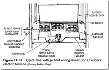
A typical example of line voltage field wiring is shown in Figure 14-13. Line voltage wiring involves the connection of the furnace to the building power supply. Line voltage wiring runs directly from the building power panel to a fused disconnect switch. From there, the wiring runs to terminals L1 and L2 on the power-supply terminal block.
The unit must be properly grounded either by attaching a grounded conduit for the supply conductors (knockouts in the side panels of Fedders electric furnaces are provided for this purpose) or by connecting a separate wire from the furnace ground lug to a suit- able ground.
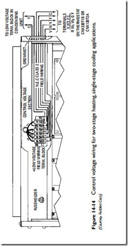
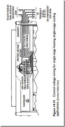
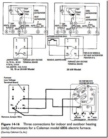
The external control voltage circuitry consists of the wiring between the thermostat and the low-voltage terminal block located in the control voltage section of the furnace. Instructions for control voltage wiring are generally shipped with the thermostat.
Some typical examples of control voltage field wiring used with Fedders electric furnaces are shown in Figures 14-14 and 14-15. Control voltage field wiring connections used with Coleman electric furnaces are shown in Figure 14-16.
The National Electrical Code requires that furnaces larger than 10 kW be supplied with branch circuit fusing. Power connections on units of this size are usually made to lugs on the fuse blocks.
Blowers and Motors
The blowers and motors used with electric furnaces are identical to those used in gas-fired furnaces. Read the section Blowers and Motors in Chapter 11, “Gas Furnaces” for additional information.
Air Delivery and Blower Adjustment
It is sometimes necessary to adjust the blower speed to produce a temperature rise through the furnace that falls within the limits stamped on the furnace nameplate. Blower adjustment procedures are described in full detail in Chapter 11, “Gas Furnaces.”
Air Filter
The air filters used in electric forced-warm-air furnaces are either permanent types that can be removed and cleaned on a periodic basis or replaceable, throwaway filters.
More detailed information concerning furnace air filters is contained in Chapter 12, “Air Cleaners and Filters” of Volume 3. See also the comments about air filters in the section Maintenance and Operating Instructions in this chapter.
Air Conditioning
A furnace should be installed in parallel or on the upstream side of the cooling unit to avoid condensation in the heating section. Parallel installation will require dampers or some other means to prevent cool air from entering the furnace.
The air conditioning component of a typical electric heating and cooling system generally consists of an outdoor condensing unit, indoor coils, and a cabinet to house the cooling coils. Most furnace manufacturers provide detailed instructions for adding air conditioning to the heating unit. The important thing to remember is to size the ducts for the larger volume of air used in air conditioning.
Additional information about air conditioning can be found in Chapters 8, 9, and 10 in Volume 3.


