DEVELOPMENT OF CIRCUIT 2
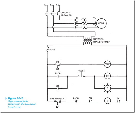
The schematic diagram for circuit 2 is shown in Figure 10–7. Notice this schematic shows both the control circuit and the motor connection. This circuit is designed to turn off a compressor if the pressure in the system reaches a predetermined
level. If the pressure becomes high enough to cause the pressure switch contacts to close, the compressor motor will not only be disconnected from the power line, but a warning light will also be turned on. Once the warning light has been turned on, the system must be manually reset by the service technician before the compressor can be restarted by the thermostat. The operation of the circuit is as follows:
When the thermostat contact closes, a circuit is completed to M motor starter coil. When M coil energizes, M contacts close and connect the compressor to the three-phase power line. When the temperature decreases, the thermostat contacts open and deenergize M coil. When M coil deenergizes, M contacts open and disconnect the compressor from the power line. Notice that in the normal action of this circuit, the compressor is controlled by the thermostat.
Now assume that the thermostat contacts are closed and that the compressor is connected to the power line. Also assume that the pressure in the system becomes too great and that the contacts of the pressure switch close. When the pressure switch contacts close, PSCR (pressure switch control relay) coil energizes. This causes both
PSCR contacts to change position. When the normally closed PSCR contact opens, the circuit to M coil is broken. This causes the compressor to be disconnected from the line. When the normally open PSCR contact closes, a circuit is completed to CR (control relay) coil. When CR coil energizes, both CR contacts change position. The normally open CR contact closes to maintain a circuit to CR coil in the event that the pressure in the system decreases and opens the pressure switch contacts. This would cause PSCR relay to deenergize and return both PSCR contacts to their normal position. The normally closed CR contact will open. This prevents M coil from being energized by the thermostat if PSCR contact should reclose. Notice that the warning light is connected in parallel with the coil of CR relay. The warning light will be turned on as long as CR relay coil is turned on. As long as CR relay is energized, the compressor cannot be restarted by the thermostat.
Now assume that the pressure in the system has returned to normal and the problem that caused the excessive pressure has been corrected. When the pressure switch contact reopened, PSCR coil deenergized and reset both PSCR contacts to their normal position. When the service technician presses the reset button, CR coil deenergizes and both CR contacts return to their normal positions.
The circuit is now back in its original position and ready for normal operation.
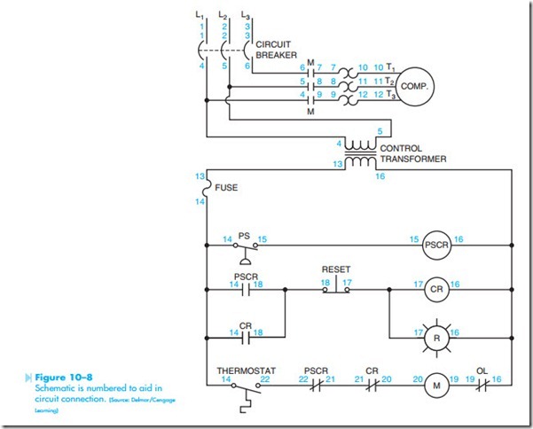
This schematic diagram is now being developed into a wiring diagram. As before, the schematic is numbered in the same manner as the first example. The numbered schematic is shown in Figure 10–8. Notice that all components that are electrically tied together have the same number. Also notice that no number set has been used more than once.
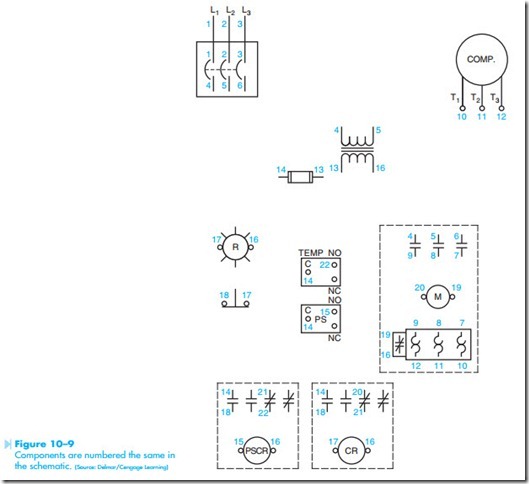
The control components are shown in Figure 10–9. Notice that the numbers on the components correspond with like numbers on the schematic diagram. For example, on the schematic diagram the primary of the control transformer is numbered 4 and 5. The secondary leads are numbered 13 and 16. Notice the same is true on the wiring diagram. Note the number of each component on the schematic and then
find the corresponding number beside the proper component used on the wiring diagram.
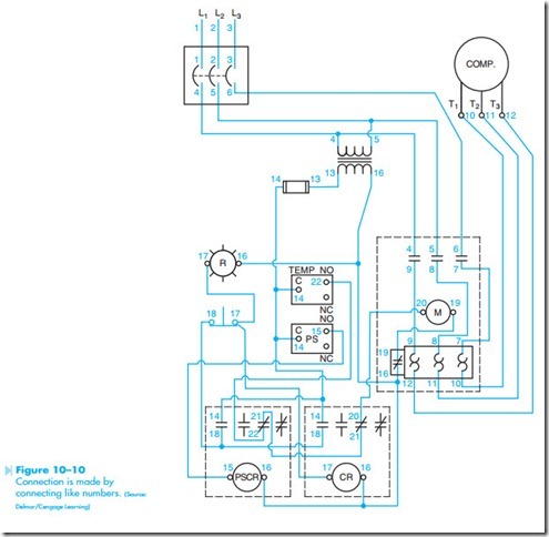
Once the components of the wiring diagram have been numbered with the same numbers as those on the schematic, the circuit can be connected by connecting like numbers. The circuit connection is shown in Figure 10–10. Again, notice that the wiring diagram appears to be completely different from the schematic, but both are the same electrically.


