Thermopilot Valves
A thermopilot valve is a 100 percent safety shutoff control for gas- fired heating equipment and appliances. It operates on current sup- plied by a thermocouple or pilot generator. This current energizes a thermomagnet, which holds the valve open after manual reset. When there is an unstable or low pilot flame or no flame at all, the current to the thermomagnet is lost. As a result, the valve closes, shutting off the gas flow.
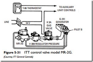
An example of a thermopilot valve operated by a thermocouple is the ITT General Controls MR-2G valve. Using it in conjunction with a solenoid gas valve provides 100 percent safety shutoff con- trol (see Figure 5-31).
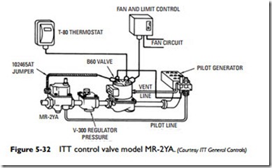
The thermomagnet of an ITT General Controls MR-2YA valve is energized by a pilot generator. It must be used with a pilot-operated diaphragm valve to provide 100 percent safety shutoff control (see Figure 5-32).
The following suggestions should be carefully observed when installing ITT thermopilot valves in order to ensure efficient valve operation:
• Locate the valve so that it is easily accessible and where the ambient temperature is below 200F° .
• Make sure the piping is clean (blow out all particles and other impurities).
• Apply thread seal sparingly to male threads only.
• Install valve with gas flow in the same direction as the arrow in the valve body is pointing.
• Use the pipe wrench on the valve body flats at the end being connected.
• Avoid stress on the valve body by aligning the inlet and outlet pipe connections.
• Check all pipe connections for gas leaks with a soap and water solution. Never use a flame.
• Check the valve with a millivolt meter (see next paragraph).
• All wiring connections should be clean and tight.
• Pilot burner should be installed on main burner so that the ignition flame will light the main burner with the pilot turned down low.
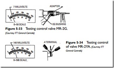
Testing an ITT General Controls MR-2G thermopilot valve with a millivolt meter requires the use of a special adapter. The adapter and thermocouple are connected to the valve as shown in Figure 5-33. Attach the meter clips as shown. Figure 5-34 illustrates the testing of an ITT MR-2YA valve. In either case, the valve should be replaced if the meter reading is above that shown on the applicable scale and the valve fails to open after following the light- ing instructions.


