Thermodynamic analysis of a centrifugal compressor
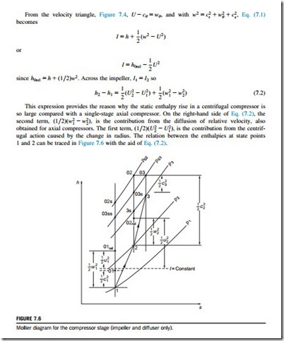
The flow through a centrifugal compressor stage is a highly complicated 3D motion and a full analysis presents many problems. Fortunately, we can obtain approximate solutions by simplifying the flow model, e.g., by adopting the so-called 1D approach that assumes that the fluid conditions are uniform over certain flow cross sections. These cross sections are conveniently taken immediately before and after the impeller as well as at inlet and exit of the entire machine. Where inlet vanes are used to give prerotation to the fluid entering the impeller, the 1D treatment is no longer valid and an extension of the analysis is then required. (Examples of 3D flows are given in Chapter 6.)
The impeller
Referring to Figure 7.4, and in particular the inlet velocity diagram, the absolute flow has no whirl component or angular momentum and cθ1 5 0. In centrifugal compressors and pumps, this is the normal situation where the flow is free to enter axially. For such a flow, the specific work done on the fluid, from Eq. (1.18b), is written as
in the case of pumps, where Hi (the “ideal” head) is the total head rise across the pump excluding all internal losses. In high-pressure ratio compressors, it may be necessary to impart prerotation to the flow entering the impeller as a means of reducing a high relative inlet velocity. The effects of high relative velocity at the impeller inlet are experienced as Mach number effects in compressors and cavitation effects in pumps. The usual method of establishing prerotation requires the installation of a row of inlet guide vanes upstream of the impeller, the location depending upon the type of inlet. Unless contrary statements are made, it will be assumed for the remainder of this chapter that there is no prerotation (i.e., cθ1 5 0).
The diffuser
The diffuser is an important element of a compressor or pump. Its purpose is to reduce the velocity of the flow leaving the impeller resulting in an increase in pressure. The diffuser can be simply depicted as a nonrotating channel whose flow area increases in the direction of flow (Figure 7.7).
Although the basic diffuser appears to be a geometrically simple device, it is beset by two serious fluid mechanical problems. The primary problem is the tendency of the boundary layers to
separate from the diffuser walls if the local rate of diffusion is too rapid resulting in flow mixing and large losses in stagnation pressure. On the other hand, if the diffusion rate is too low, the fluid is exposed to a long length of wall and fluid friction losses again become excessive. Clearly, there has to be an optimum rate of diffusion between these two extremes for which the losses are minimized. Test results indicate that a diffuser with an included angle of about 7o or 8o gives the optimum recovery for both 2D and conical diffusers. Some further details of the performance of rectilinear diffusers taking into account the classical work of Sovran and Klomp (1967) is given later in this chapter.
Related posts:
Incoming search terms:
- centrifugal compressor velocity diagram
- centrifugal compressor diagram in thermodynamics
- velocity diagram for c
- thermodynamics in centrifugal diagram
- outer diameter of turbo compressor backward calculation
- compressors and pumps thermodynamics
- compressor impeller cross area
- centrifugal pump thermodynamics
- centrifugal pump thermo
- centrifugal compressor velocity/diagram
- velocity diagram of radial centrifugal fan


