Introduction
This chapter is concerned with the elementary flow analysis and preliminary design of work- absorbing turbomachines comprising pumps, low-speed fans, and compressors. The major part of the analysis is centered on the compressor since the basic action of all these machines is, in most respects, similar.
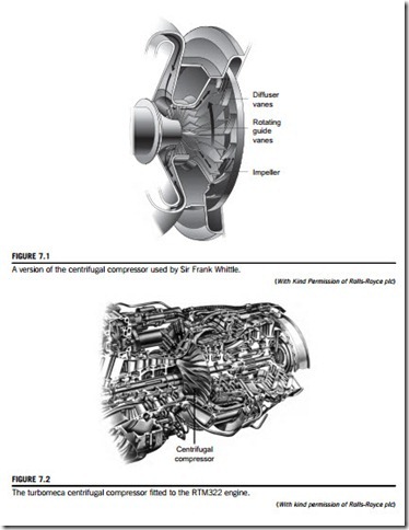
Turbomachines employing centrifugal effects for increasing fluid pressure have been in use for more than a century. The earliest known machines using this method were hydraulic pumps followed later by ventilating fans and blowers. Cheshire (1945) recorded that a centrifugal compressor was incorporated in the build of the Whittle turbojet engine. Figure 7.1 is a version of this compressor illustrating, for that period, a rather complex flow path of the air. By way of contrast, a modern centrifugal compressor is shown as one component of a composite compressor of a jet engine in Figure 7.2.
Development of the centrifugal compressor for aircraft propulsion continued into the mid-1950s but, long before this, it had become clear that axial-flow compressors were better able to meet the needs of larger engines. Not only were the frontal area (and drag) smaller with engines using axial compressors but also the efficiency for the same duty was better by as much as 3 or 4%. However, for very small compressors with low flow rates, the efficiency of axial compressors drops sharply, blading is small and difficult to make accurately, and the centrifugal compressor is again the king. Many applications are found in small gas turbines for road vehicles and commercial helicopters as well as bigger applications, e.g., diesel engine turbochargers, chemical plant processes, factory workshop air supplies, and large-scale air-conditioning plant.
Centrifugal compressors were the choice for refrigerating plants and compression-type heat pumps used in district heating schemes described by Hess (1985). These compressors with capacities ranging from below 1 MW up to nearly 30 MW were preferred because of their good economy, low maintenance, and absolute reliability.
Palmer and Waterman (1995) gave some details of an advanced two-stage centrifugal compressor used in a helicopter engine with a pressure ratio of 14, a mass flow rate of 3.3 kg/s, and an overall
total-to-total efficiency of 80%. Both stages employed backswept vanes (approximately 47o) with a
low aerodynamic loading achieved by having a relatively large number of vanes (19 full vanes and 19 splitter vanes). Some basic details are given in this chapter for calculating the performance of centrifugal compressors with backward swept impeller vanes. Figure 7.3 is a picture of a compressor that features a high-performance centrifugal compressor impeller with 15 backswept main vanes (and 15 splitter vanes) and its surrounding wedge diffuser is fitted with 24 vanes.
Some definitions
As well as axial-flow compressors and fans, which we dealt with in Chapter 5, most of the pressure-increasing turbomachines in use are of the radial-flow type and vary from fans that pro- duce pressure rises equivalent to a few millimeters of water to pumps producing pressure heads of many hundreds of meters of water. The term pump refers to machines that increase the pressure of a flowing liquid. The term fan is used for machines imparting only a small increase in pressure to a flowing gas. In this case, the pressure rise is usually so small that the gas can be considered as being incompressible. A compressor gives a substantial rise in pressure to a flowing gas. To make a distinction, a compressor can be defined as a pressure-increasing machine where the density ratio across it is 1.05 or greater.
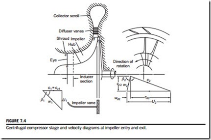
A centrifugal compressor or pump consists essentially of a rotating impeller followed by a diffuser. Figure 7.4 shows diagrammatically the various elements of a centrifugal compressor. Fluid is drawn in through the inlet casing into the eye of the impeller. The function of the impeller is to increase the energy level of the fluid by whirling it outward, thereby increasing the angular momentum of the fluid. Both the static pressure and the velocity are increased within the impeller. The purpose of the diffuser is to convert the kinetic energy of the fluid leaving the impeller into pressure energy. This process can be accomplished by free diffusion in the annular space surrounding the impeller or, as indicated in Figure 7.4, by incorporating a row of fixed diffuser vanes that allows the diffuser to be made very much smaller. Outside the diffuser is a scroll or volute whose function is to collect the flow from the diffuser and deliver it to the outlet pipe. In low-speed compressors and pump applications where simplicity and low cost count for more than efficiency, the volute follows immediately after the impeller (as shown later in Figures 7.22 and 7.23).
The hub is the curved surface of revolution of the impeller a-b; the shroud is the curved surface c-d forming the outer boundary to the flow of fluid. At entry to the impeller, the relative flow has a velocity w1 at angle β1 to the axis of rotation. This relative flow is turned into the axial direction by the inducer section or rotating guide vanes as they are sometimes called. The inducer starts at the eye and usually finishes in the region where the flow is beginning to turn into the radial direction. Some compressors of advanced design extend the inducer well into the radial flow region, apparently to reduce the amount of relative velocity diffusion.
To simplify manufacture and reduce cost, the impellers of many fans and pumps are confined to a 2D radial section as shown in Figure 7.5. With this arrangement some loss in efficiency can be
expected. For the purpose of greatest utility, relations obtained in this chapter are generally in terms of the 3D compressor configuration as shown in Figure 7.4.


