Performance of centrifugal compressors
Determining the pressure ratio
Consider a centrifugal compressor having zero inlet swirl, compressing a perfect gas. With the usual notation, the energy transfer is
where Mu 5 U2/a01 is now defined as a blade Mach number.
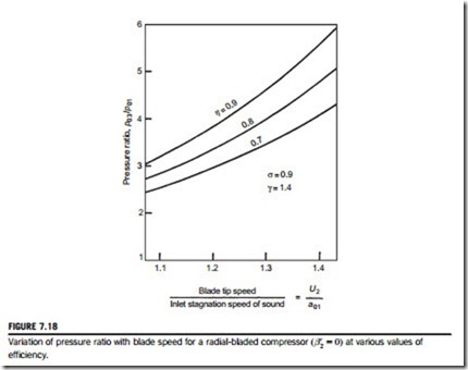
It is useful and of interest to calculate the variation of the pressure ratio of a radially vaned ðβ0 5 0Þ centrifugal air compressor to show the influence of blade speed and efficiency on the per- formance. With γ 5 1.4 and σ 5 0.9 (i.e., using the Stanitz slip factor, σ 5 1-1.98/Z) and assuming Z 5 20, the results evaluated are shown in Figure 7.18 It is clear that both the efficiency and the blade speed have a strong effect on the pressure ratio.
In the 1970s the limit on blade speed due to centrifugal stress was about 500 m/s and compressor efficiency seldom exceeded 80%. With a slip factor of 0.9, a radial-vaned impeller and an inlet temperature of 288 K, the pressure ratio achieved was barely above 5. More recently quite significant improvements in the performance of centrifugal compressors have been obtained, brought about by the development of computer-aided design and analysis techniques. According to Whitfield and Baines (1990), the techniques employed consist of “a judicious mix of empirical cor- relations and detailed modeling of the flow physics”! However, it is possible to use these computer packages and arrive at a design solution without any real appreciation of the flow phenomena involved. In all compressors, the problematic part of the flow process is the diffusion; boundary layers are very prone to separate and the flow can become very complicated with separated wakes in the flow and unsteady flow downstream of the impeller. It must be stressed that a broad
understanding of the flow processes within a centrifugal compressor is still a vital requirement for the more advanced student and for the further progress of new design methods.
A characteristic of all high-performance compressors is that as the design pressure ratio has increased, so the range of mass flow between surge and choking has diminished. In the case of the centrifugal compressor, choking can occur when the Mach number entering the diffuser passages is just in excess of unity. This is a severe problem that is aggravated by any shock-induced separation of the boundary layers on the vanes, which will worsen the problem of flow blockage.
Effect of backswept vanes
Came (1978) and Whitfield and Baines (1990) have commented upon the trend of obtaining higher pressure ratios from single-stage compressors leading to more highly stressed impellers. The increasing use of backswept vanes and higher blade tip speeds results in higher direct stress in the impeller and bending stress in the nonradial vanes. However, methods of computing the stresses in impellers are available, capable of determining both the direct and the bending stresses caused by the impeller rotation.
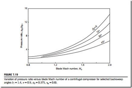
The effect of using backswept impeller vanes on the pressure ratio is shown in Figure 7.19 for a range of blade Mach numbers. The use of backswept vanes at a given blade speed causes some loss in pressure ratio. In order to maintain a given pressure ratio, it is therefore necessary to increase the design speed, which increases the blade stresses.
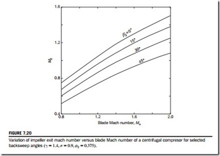
With high blade tip speeds the Mach number of the absolute flow leaving the impeller may exceed unity. As this Mach number can be related to the Mach number at entry to the diffuser vanes, it is of some advantage to be able to calculate the former.
Assuming a perfect gas, the Mach number at impeller exit M2 can be written as
where the values of A and B are given in Table 7.1 and from which the curves of M2 against Mu in Figure 7.19 have been calculated.
Whitfield and Baines (1990) assert that the two most important aerodynamic parameters at impeller exit are the magnitude and direction of the absolute Mach number M2. If M2 has too high a value, the process of efficient flow deceleration within the diffuser itself is more difficult leading to high friction losses as well as the increased possibility of shock losses. If the flow angle α2 is
large, then the flow path in the vaneless diffuser will be excessively long resulting in high friction losses and possible stall and flow instability. Several researchers, e.g., Rodgers and Sapiro (1972), have shown that the optimum flow angle is in the range 60o , α2 , 70o.
Backswept vanes give a reduction of the impeller discharge Mach number, M2, at any given tip speed. A designer making the change from radial vanes to backswept vanes will incur a reduction in the design pressure ratio if the vane tip speed remains the same. To recover the original pressure ratio, the designer needs to increase the blade tip speed, which, in turn, increases the discharge Mach number. Fortunately, it turns out that this increase in M2 is rather less than the reduction obtained by the use of backsweep.
Illustrative exercise
ratio at this point is 6.9 and, from Figure 7.20, the value of M2 5 1.3. Choosing another impeller with a backsweep angle, β20 5 30o, the pressure ratio is 5.0 from Figure 7.19 at the same value of Mu. So, to restore the original pressure ratio of 6.9 the blade Mach number must be increased to
Mu =1.81. At this new condition a value of M2 5 1.178 is obtained from Figure 7.20, a significant reduction from the original value. Greater values of backsweep may produce even further benefits! The absolute flow angle can now be found from the exit velocity triangle, Figure 7.12:
Assuming again the values σ 5 0.9, σ2 5 0.375, then with β0 5 0o, the value of α2 5 67.38o. Similarly, with β0 5 30o, the value of α2 5 62o, i.e., both values of α2 are within the prescribed acceptible range.
Kinetic energy leaving the impeller
According to van den Braembussche (1985), “the kinetic energy available at the diffuser inlet easily amounts to more than 50% of the total energy added by the impeller.” Using the foregoing analysis, we can determine whether this statement is true or not. If the magnitude of the kinetic energy is so large, then the importance of efficiently converting this energy into pressure energy can be appreciated. The conversion of the kinetic energy to pressure energy is considered in the following sec- tion on diffusers.
We can define the fraction of the kinetic energy at impeller exit to the specific work input as
Illustrative exercise
Determine fKE assuming that β2 5 0; σ 5 0:9; ηI 5 0:8; pr 5 4; and γ 5 1:4: Note: It is very convenient to assume that Figures 7.19 and 7.20 can be used to derive the values of the Mach numbers Mu and M2. From Figure 7.19, we get Mu 5 1.32 and from Figure 7.20, we get M2 5 1.13. Substituting these results into Eq. (7.48), we obtain the result
This calculation has thus verified the assertion of van den Braembussche (given previously) that the kinetic energy available at diffuser inlet amounts to more than 50% of ΔW. This, clearly, is an extra incentive to seek an efficient diffuser system!
Calculations of fKE at other pressure ratios and sweepback angles show that its value remains about 0.52 provided that σ and η1 do not change.
EXAMPLE 7.4
Air at a stagnation temperature of 22oC enters the impeller of a centrifugal compressor in the axial direction. The rotor, which has 17 radial vanes, rotates at 15,000 rev/min. The stagnation pressure ratio between diffuser outlet and impeller inlet is 4.2 and the overall efficiency (total- to-total) is 83%. Determine the impeller tip radius and power required to drive the compressor when the mass flow rate is 2 kg/s and the mechanical efficiency is 97%. Given that the air den- sity at impeller outlet is 2 kg/m3 and the axial width at entrance to the diffuser is 11 mm, determine the absolute Mach number at that point. Assume that the slip factor σ 5 1-2/Z, where Z is the number of vanes. (For air, take γ 5 1.4 and R 5 0.287 kJ/(kg K).)
Solution
Although the absolute Mach number at the impeller tip can be obtained almost directly from Eq. (7.46a), it may be instructive instead to find it from its basic definition:


