Electrical faults
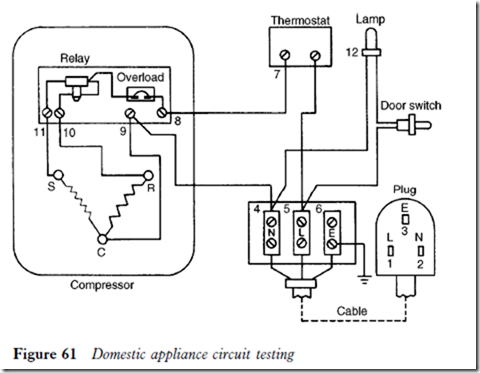
The diagnosis of electrical faults on components and compressors has already been dealt with in Chapter 7. The following procedure may be carried out to quickly pinpoint the faulty component and to eliminate unnecessary disman- tling. The electrical circuit is tested for continuity from the terminal board of the circuit. The typical electrical circuit in Figure 61 has been chosen for the test procedure.
Steps 1 and 2 of the test procedure can be disregarded if the refrigerator or freezer has an interior light. This will come on when the appliance door is opened, unless the light bulb itself is defective.
The procedure is as follows:
1 Test for continuity from points 1 to 2, which will test the whole circuit.
2 Test from point 3 to points 1 and 2 to reveal any earth fault.
3 Test from points 1 to 8, which eliminates half of the circuit.
4 If the fault is in section 1 to 8, test between points 1 and 5 to determine if the fault is due to a loose connection, a defective cable or a blown fuse.
5 Should the fault be located in section 5 to 8, then the thermostat must be considered inoperative because the interior light and door switch will be isolated when the door is closed.
6 If the fault is in the compressor half of the circuit, it should be located in a similar manner by dividing into sections until it has been finally determined.
When an ohmmeter is used to test for continuity, it should normally be set to read off the ð1 scale. If the total resistance of the circuit is in excess of 100 ohms, the ð10 scale will be required; reset to the ð1 scale when the faulty section is isolated to less than 100 ohms.
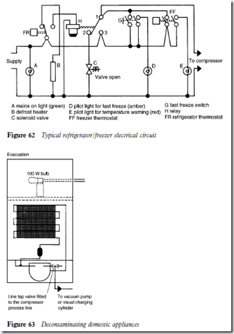
Figure 62 shows a typical refrigerator/freezer electrical circuit.
Decontaminating domestic systems
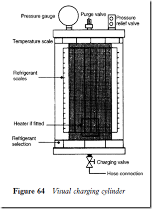
With liquid flushing using R11 no longer permissible the previously described dilution method can be carried out (see Chapter 16).
Refrigerant charging in domestic appliances
The principles of refrigerant charging have been covered in Chapter 4.
Domestic refrigerators and freezers operate with very small refrigerant charges, and the charge must be administered accurately. This can be best
achieved by using a visual charging cylinder, sometimes called a dial-a-charge (Figure 64).
This is basically a small refrigerant cylinder with a liquid-indicating sight glass or tube. In front of the sight glass and surrounding the cylinder and sight glass is a rotating screen upon which are graduated scales for the common refrigerants, R12, R22 and R502. Above the refrigerant scales is a temperature range.
Fitted to the top of the cylinder assembly are a pressure gauge; a purging valve, which is normally a Schraeder type; and, if a heater is incorporated, a pressure relief valve for the cylinder protection. At the base of the cylinder is a charging valve and hose connection.
Filling the cylinder
1 Obtain a service cylinder of the correct refrigerant. Connect it to the visual charger with a suitable hose.
2 Open the valve on the service cylinder and invert the cylinder.
100 Refrigeration Equipment
3 Slacken the hose connection at the charging valve to purge air from the hose. Tighten the hose connection.
4 Open the charging valve to allow refrigerant liquid to flow by gravity into the cylinder. Observe the sight glass: when liquid flow ceases, depress the purge valve and gently vent off a small amount of refrigerant vapour. When a pressure difference between the charging cylinder and the service cylinder is created, the liquid will begin to flow again. Repeat this opera- tion until the required amount of refrigerant is in charging cylinder.
5 Close the valves on both the visual charger and the service cylinder.
6 Disconnect the service cylinder.
Charging the system
1 Assuming a line tap valve has been installed and the system evacuated, connect the hose to the charging valve and the line tap valve.
2 Open the charging valve and slacken off the hose connection to purge air from the hose. Close the valve.
3 Note the ambient temperature. Rotate the screen until the required refrig- erant scale lines up with the ambient temperature on the temperature scale.
4 Note the level of the refrigerant in the sight glass.
5 Open the line tap valve fully and slowly meter the prescribed amount of refrigerant into the system. If the visual charger has a heater this can be energized before opening the line tap valve to create a pressure difference between the charging cylinder and the system.
6 When the charge has been administered as indicated by the sight glass, close the charging valve.
7 Allow a few minutes for the liquid in the hose to vaporize and the system pressure to equalize. Then close the line tap valve.
8 Disconnect the visual charger and leak test the system.
Alternative method of charging
If a refrigerant charge cannot be accurately measured by using a visual charger, it must be drawn into the system by the compressor from the low side. It is imperative that this is carried out slowly to eliminate the risk of overcharging, which could damage the compressor.
By allowing small amounts of refrigerant vapour into the system, and observing the frost line on the evaporator, overcharging can be prevented.
When the frost line reaches the location of the thermostat bulb it is always advisable to stop charging and allow sufficient time for the system to reach average evaporating temperature and start to cycle. Should frosting back occur, purge off the surplus refrigerant in small amounts from the line tap valve connection.
Reference to the compressor nameplate should be made to determine the running current.
Refrigerant charges are normally stamped on the refrigerator model plate. The charge may be given in ounces or grams according to the age of the refrigerator. These quantities can be easily converted: 1 ounce D 28.35 grams. For example, 150 grams is equivalent to 150/28.35 D 5.29 ounces; 6.5 ounces is equivalent to 6.5 ð 28.35 D 184.27 grams.
Remember, an undercharge of refrigerant will result in long running periods or continuous running. An overcharge of refrigerant will result in frosting back, overheating, increased running costs and could possibly damage the compressor.


