Low speed ducted fans
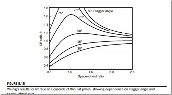
In essence, these widely used fans are simply low-speed single-stage compressors with a low pressure (and temperature) rise, so that much of the foregoing theory of this chapter is valid for this class of machine. However, because of the high space-chord ratio used in many of these fans, a simplified theoretical approach based on isolated aerofoil theory is often used. This method can be of use in the design of ventilating fans in which aerodynamic interference between adjacent blades can be assumed negligible. Attempts have been made to extend the scope of isolated aerofoil theory to less widely spaced blades by the introduction of an interference factor; for instance, the ratio k of the lift force of a single blade in a cascade to the lift force of a single isolated blade. As a guide to the degree of this interference, an exact mathematical solution obtained by Weinig (1935) and used by Wislicenus (1947) for a row of thin flat plates is of value and is shown in Figure 5.18. This illustrates the dependence of k on space-chord ratio for several stagger angles. The rather pronounced effect of stagger for moderate space-chord ratios should be noted as well as the asymptotic convergence of k toward unity for higher space-chord ratios.
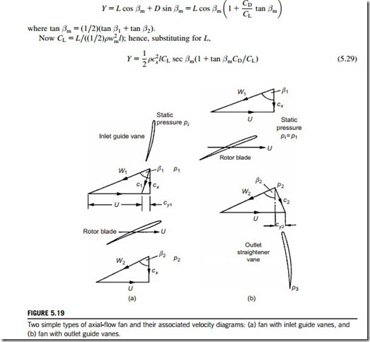
Two simple types of axial-flow fan are shown in Figure 5.19 in which the inlet and outlet flows are entirely axial. In the first type (a), a set of guide vanes provides a contra-swirl and the flow is restored to the axial direction by the rotor. In the second type (b), the rotor imparts swirl in the direction of blade motion and the flow is restored to the axial direction by the action of outlet straighteners (or outlet guide vanes). The theory and design of both these types of fan have been investigated by Van Niekerk (1958) who was able to formulate expressions for calculating the optimum sizes and fan speeds using blade element theory.
Note that the analysis in this section uses cartesian (x and y) coordinates in order to be consis- tent with the low-speed cascade analysis presented in Section 3.4.
Lift and drag coefficients
For a low-speed fan the stage loading factor may be expressed in terms of the lift and drag coefficients for the rotor. From Figure 3.12, replacing αm with βm, the tangential blade force on the moving blades per unit span is
The work done by each moving blade per second is YU and is transferred to the fluid through one blade passage during that period. Thus, YU 5 ρscx(h03 2 h01).
Therefore, the stage loading factor may now be written as
Blade element theory
A blade element at a given radius can be defined as an aerofoil of vanishingly small span. In fan design theory, it is commonly assumed that each such element operates as a 2D aerofoil, behaving completely independently of conditions at any other radius. Now the forces impressed upon the fluid by unit span of a single stationary blade have been considered in some detail already, in Chapter 3. Considering an element of a rotor blade dr, at radius r, the elementary axial and tangential forces, dX and dY, respectively, exerted on the fluid are, referring to Figure 3.12,
The torque exerted by one blade element at radius r is r dY. If there are Z blades, the elementary torque is
Blade element efficiency
Consider the fan type shown in Figure 5.19(a) fitted with guide vanes at inlet. The pressure rise across this fan is equal to the rotor pressure rise, p2 2 p1, minus the drop in pressure across the guide vanes, pi 2 p1. The ideal pressure rise across the fan is given by the product of density and CpΔT0. Fan designers define a blade element efficiency as
Now, since the change in swirl velocity across the rotor is equal and opposite to the swirl produced by the guide vanes, the work done per unit mass flow, CpΔT0 is equal to Ucy1. Thus, the second term in Eq. (5.39) is
Lift coefficient of a fan aerofoil
For a specified blade element geometry, blade speed, and lift-drag ratio, the temperature and pressure rises can be determined if the lift coefficient is known. An estimate of lift coefficient is most easily obtained from 2D aerofoil potential flow theory. Glauert (1959) showed, for isolated aero- foils of small camber and thickness, that
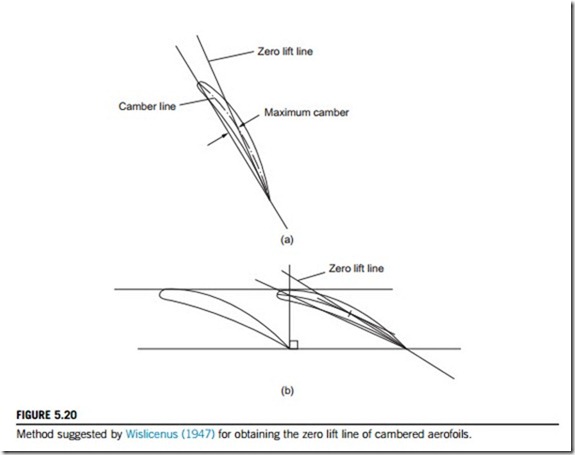
where α is the angle between the flow direction and the line of zero lift of the aerofoil. For an isolated, cambered aerofoil Wislicenus (1947) suggested that the zero lift line may be found by joining the trailing edge point with the point of maximum camber, as depicted in Figure 5.20(a). For fan blades experiencing some interference effects from adjacent blades, the modified lift coefficient of a blade may be estimated by assuming that Weinig’s results for flat plates (Figure 5.18) are valid for the slightly cambered, finite thickness blades, and
When the vanes overlap (as they may do at sections close to the hub), Wislicenus suggested that the zero lift line may be obtained by the line connecting the trailing edge point with the maxi- mum camber of that portion of blade that is not overlapped, Figure 5.20(b).
The extension of both blade element theory and cascade data to the design of complete fans was discussed in considerable detail by Wallis (1961).


