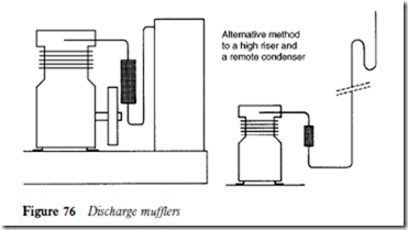
Discharge line mufflers
In the event of noise or vibration from gas pulsations, discharge mufflers are recommended and must be installed for the free draining of oil.
As previously stated, when compressors are idle the oil adhering to the inner surfaces of the discharge line risers will drain to the bottom of the risers. With a 3 m riser, plus the discharge muffler, the amount of oil can be quite considerable.
It is therefore advisable to loop the discharge line towards the floor to form a trap so that oil cannot drain to the compressor head. This trap will also collect any liquid refrigerant which may condense during the off cycle. It is especially important when the discharge line is in a cooler location than the condenser/receiver. Mufflers are normally installed vertically near the condensing unit to provide efficient oil movement. Figure 76 shows a discharge muffler installed in a discharge line loop.
Parallel pipework
When compressors are installed in parallel and share common suction and discharge lines, they are usually open-type units. Hermetic and semi-hermetic units are not used in case of a motor failure. The high temperatures resulting from the motor failure of one motor compressor can cause a chemical break- down of the refrigerant and oil, resulting in the contamination of the whole system.
However, two or more hermetic or semi-hermetic units can be used to accommodate a common load. When this is required each compressor is connected to an independent circuit within the evaporator and the condenser, so that they function without the possibility of cross-contamination. A single condenser is normally preferred for ease of control, but a separate condenser may be used for each compressor.
Discharge lines
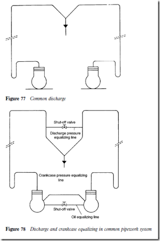
Discharge lines should be installed so that the horizontal section is pitched downwards to join the common line. This will provide a free draining trap, preventing oil drain back to the idle compressor.
When the condenser is located above the compressors, separate risers should be used. Oil traps should be included at the base of each riser if the net lift to the condenser is more than 2 m. If the riser height is less than 2 m the oil traps may be omitted.
Figure 77 shows a basic pipework arrangement for discharge lines.
Discharge line equalizing
When individual condensers are installed, discharge lines must be equalized before they enter the condensers to allow them to function as one (Figure 78).
The pressure drop within equalizing lines is critical. For example, assume a pressure drop of 0.03 bar (0.5 psig) in the equalizer line. The pressure differen- tial between an idle and an active condenser will cause condensed refrigerant from the active condenser to back through the liquid line to the idle condenser in an effort to equalize.
Crankcase equalizing
Obviously it is also necessary to prevent unequal oil distribution between the crankcases of the compressors. This is achieved by connecting an equalizer line to tappings provided (Figure 78).
The equalizer line size must be equal to the size of the tapping union. It is also essential that the compressors are mounted on the same level or that the oil levels are at the same height; compressor mounts can be adjusted to make this possible.

