Automatic Controls on Gas-Fired Water Heaters
The principal automatic controls used to govern the operation of a gas-fired water heater are as follows:
1. Thermostatic valve
2. Automatic pilot valve
3. Manual gas valves
4. Main gas–pressure regulator
5. Pilot gas–pressure regulator
6. Temperature and pressure relief valves
7. Automatic gas shutoff device
8. Pilot burner
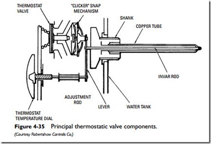
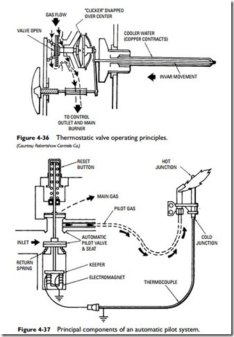
A thermostatic valve (see Figures 4-35 and 4-36) is used to con- trol the gas input to the burners in relation to the water tempera- ture in the storage tank. Thermostatic water temperature controls are usually direct, snap-action bimetallic devices that react to a drop in the temperature of the water in the storage tank. This drop in temperature causes a thermal element immersed in the stored hot water to contract and, through mechanical linkage, to open the main gas valve on the unit. When the water in the tank reaches a selected, predetermined setting, the thermal element expands and closes the main gas valve. These thermostatic valves normally oper- ate at a temperature differential of approximately 12°F. In other words, if set to shut off the gas to the main burner when the tank water temperature reaches 140°F, they will react to open the valve when the temperature drops to 128°F.
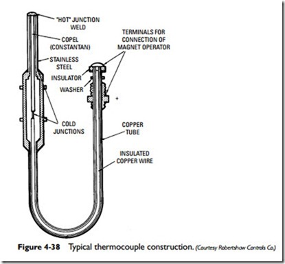
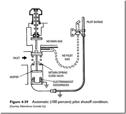
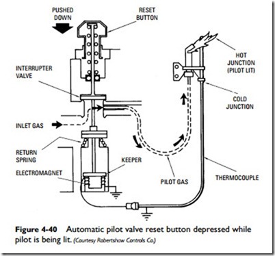
Another important control on a gas-fired water heater is the automatic pilot valve, which operates on the thermocouple princi- ple (see Figures 4-37 and 4-38). This control automatically shuts off the gas when pilot outage or improper ignition conditions occur. When the electromagnet is deenergized, the magnet allows the return spring to close the automatic pilot valve and shut off the gas supply to both the main burner and the pilot. The 100 percent automatic pilot shutoff condition is shown in Figure 4-39. As
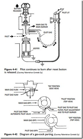
shown in Figure 4-40, the reset button must be depressed while the pilot is being relit. If the flame is established, the pilot will continue to burn after the reset button is released (see Figure 4-41).
Manual gas valves (gas cocks) function as a backup safety system to the automatic pilot valve by providing manual control of the main burner and pilot burner gas supply (see Figure 4-42). The manual gas valve is also used with the automatic pilot valve to pro- vide safe pilot lighting by ensuring that only pilot gas is flowing during the pilot lighting operation.
Both pilot gas– and main gas–pressure regulators are used on gas-fired water heaters. The pilot gas–pressure regulator is used to regulate the pressure of the gas flowing to the pilot. The main gas–pressure regulator performs the same function for gas flowing to the main burners. These gas-pressure controls have been manda- tory on gas-fired water heaters since 1972.
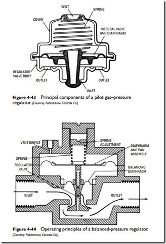
Schematics of several types of pressure regulators used on water heaters are shown in Figures 4-42, 4-43, and 4-44. These devices
operate on the balanced-pressure principle; that is to say, a main pressure diaphragm and a balancing diaphragm act to balance out or cancel the differences in inlet and outlet pressures caused by pressure variations.
Domestic gas water heater combination controls provide for main gas–pressure regulation by incorporating a pressure regulator in the control. Independent pilot gas–pressure regulation is optional (see Combination Gas Controls in this chapter).
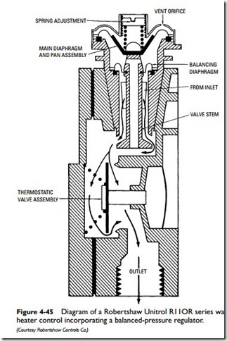
The schematic of a Robertshaw pilot gas–pressure regulator is shown in Figure 4-45. This particular pressure regulator has the approximate diameter of a penny and is inserted downstream from the pilot filter.
The following three types of safety controls (individually or in combination) are also found on water heaters:
1. Automatic gas shutoff device
2. Pressure relief valve
3. Temperature relief valve
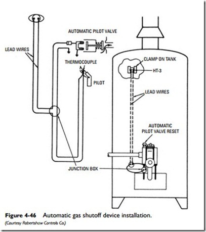
An automatic gas shutoff device is designed to shut off all gas to the water heater when excessively high water temperature conditions occur. In most automatic gas shutoff systems, this device operates in conjunction with the automatic pilot valve in the pilot safety shutoff circuit. The automatic shutoff device is generally set to shut off the automatic pilot valve when the water temperature in the storage tank approaches 210°F.
A typical automatic shutoff device, such as the one shown in Figure 4-46, is mounted on the tank surface so as to sense the water temperature through the tank wall. These devices are normally closed electrical switches connected in series in the automatic pilot millivolt circuit. When the switch reaches its preset temperature limit, it snaps open and deenergizes the electromagnet of the auto- matic pilot valve. This allows the closure spring of the automatic pilot valve to close the valve. As a result, all gas is shut off to all burners (including the pilot burner).
When the water temperature becomes too high, the volume of water in the tank tends to expand. A temperature relief valve is
designed to release a portion of the water and at the same time introduce cold water to reduce the temperature of the remaining water. The temperature relief function must occur at or below 210°F on residential and commercial water heaters.
The purpose of a pressure relief valve is to release a portion of the water from the heater or hot-water heating system when excessive pressure conditions occur. Pressure and temperature relief valves are used on all types of tank water heaters regardless of the fuel used to heat the water. See Relief Valves in this chapter.
The pilot burner gas supply is taken off ahead of the gas valve in the thermostatic control. Pilots are usually of the safety type, functioning to shut off the gas supply if the pilot burner flame is extinguished.
Most of the control functions described in the preceding paragraphs can be combined in a single unit or combination gas control (see next section).
