Gas Supply Piping
The gas supply piping (also referred to as the gas service piping) must be sized and installed in accordance with the recommendations contained in local codes and ordinances, or, if unavailable, the provisions
of the latest edition of the National Gas Code (ANSI Z223.1) and the regulations of the National Fire Protection Association (ANSI/NFPA70). The location of the main shutoff valve will usually be specified by local codes or regulations. Consult the local codes or regulations for recommended sizes of pipe for the required gas volumes. Local codes or regulations always take precedence over national standards when there is a conflict between the two.
Generally, 1-in supply pipe is adequate for furnace inputs up to 125,000 Btu/h. A 11⁄4-in pipe is recommended for higher inputs. The inlet gas supply pipe size should never be smaller than 1⁄2 in. The gas line from the supply should serve only a single unit.
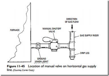
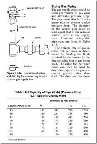
A drip leg (also called a dirt leg or a dirt trap) should be installed at the bottom of the gas supply riser to collect moisture or impurities carried by the gas. A manual main shutoff valve should be installed either on the gas supply riser or on the horizontal pipe between the riser and ground union joint (Figures 11-45 and 11-46). The location of the main shutoff valve will usually be specified by local codes and regulations.
As shown in Figure 11-45, the ground union joint should be installed between the manual main shutoff valve and the gas control valve on the furnace or boiler. The ground union joint provides easy access to the gas controls on the unit for servicing or repair.
Sizing Gas Piping
The gas supply pipe should be sized per volume of gas used and allowable pressure drop. The pipe must also be of adequate size to prevent undue pressure drop. The diameter of the supply pipe must at least equal that of the manual shutoff valve in the supply riser. Minimum acceptable pipe sizes are listed in Table 11-3.
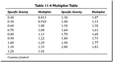
The volume rate of gas in cubic feet per hour is deter- mined by dividing the Btu/h required by the furnace by the Btu per cubic foot of gas being used. The cubic feet per hour value can then be used to determine pipe size for gas of a specific gravity other than 0.60. The data used for these
calculations are listed in Tables 11-3 and 11-4. The procedure is as follows:
1. Multiply the cubic feet per hour required by the multiplier (Table 11-4).
2. Find recommended pipe size for length of run in Table 11-3.
Tables 11-3 and 11-4 apply to the average piping installation where four or five fittings are used in the gas piping to the furnace. Existing pipe should be converted to the proper size of pipe where necessary. In no case should pipe less than 3⁄4-in diameter be used. Any extensions to existing piping should conform to Tables 11-3 and 11-4.
Related posts:
Incoming search terms:
- how to increase air supply to a gas furnace
- what is the normal btu furnace size that can be connected by a 1/2 inch gas line
- AHU fm gas piping
- required gas supply to furnace
- shutoffvalve and union location for furnace
- sizing gas line for furnace
- supply of Piping
- what size black pipe for a 100 000 btu furnace and a 50 gal hot water hearer
- What size gas line for 80 000 BTU furnace
- what size gas line for furnace
- what size gas line for home furnace
- pictures of gas supply lines on furnaces
- lp gas line install on hanging furnace
- determine gas line size for furnace
- furnace gas line code
- gas gyser pipe length rule
- gas pipe size for furnance
- gas pipe sizing made easy
- gas piping for furnace
- gas piping in gas furnaces
- gas piping sizes
- is 1/2 iron pipe enough natural gass supply for a 75000 btu furnace?
- what size gas pipe for central heating


