Voltage Drop
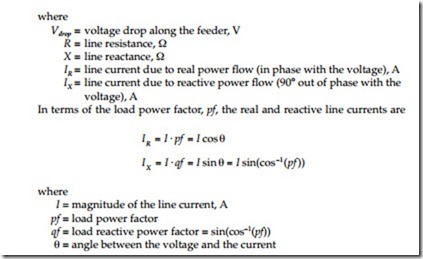
We can approximate the voltage drop along a circuit as
While just an approximation, Brice (1982) showed that IR ·R + IX ·X is quite accurate for most distribution situations. The largest error occurs under heavy current and leading power factor. The approximation has an error less than 1% for an angle between the sending and receiving end voltages up to 8° (which is unlikely on a distribution circuit). Most distribution programs use the full complex phasor calculations, so the error is mainly a consider- ation for hand calculations.
This approximation highlights two important aspects about voltage drop:
• Resistive load — At high power factors, the voltage drop strongly depends on the resistance of the conductors. At a power factor of 0.95, the reactive power factor (qf) is 0.31; so even though the resistance is normally smaller than the reactance, the resistance plays a major role.
• Reactive load — At moderate to low power factors, the voltage drop depends mainly on the reactance of the conductors. At a power factor of 0.8, the reactive power factor is 0.6, and because the reactance is usually larger than the resistance, the reactive load causes most of the voltage drop. Poor power factor significantly increases voltage drop.
Voltage drop is higher with lower voltage distribution systems, poor power factor, single-phase circuits, and unbalanced circuits. The main ways to reduce voltage drop are to:
• Increase power factor (add capacitors)
• Reconductor with a larger size
• Balance circuits
• Convert single-phase sections to three-phase sections
• Reduce load
• Reduce length
In many cases, we can live with significant voltage drop as long as we have enough voltage regulation equipment to adjust for the voltage drop on the circuit.
